Electrical installation
Wiring of digital frequency input / digital frequency output
5
216
EDKVF9333V DE/EN/FR 7.2
Wiring
Note!
ƒ We recommend to use Lenze system cables for wiring.
ƒ For self−made cables only use cables with shielded cores twisted in pairs.
B
Enable (EN)
Lamp
control (LC)
GND
Z
1
2
3
4
5
6
7
8
9
1
2
3
4
5
6
7
8
9
A
X9X10
<50m
A
B
Z
A
A
B
Z
B
Z
9300VEC019
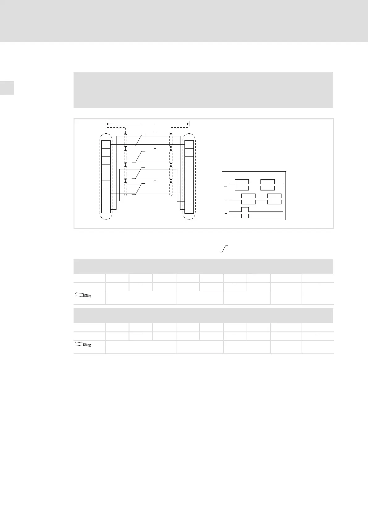
Fig. 5−33 Connection of digital frequency input (X9) / digital frequency output (X10)
X9 Slave drive Signals for CW rotation
X10 Master drive
Cores twisted in pairs
X9 − Digital frequency input
Connector: Pin, 9−pole, Sub−D
Pin 1
2 3 4 5 6 7 8 9
Signal B A A +5 V GND Z Z LC B
0.14 mm
2
(AWG 26)
0.5 mm
2
(AWG 20)
0.14 mm
2
(AWG 26)
0.5 mm
2
(AWG 20)
0.14 mm
2
(AWG 26)
X10 − Digital frequency output
Connector: Socket, 9−pole, Sub−D
Pin 1
2 3 4 5 6 7 8 9
Signal B A A +5 V GND Z Z EN B
0.14 mm
2
(AWG 26)
0.5 mm
2
(AWG 20)
0.14 mm
2
(AWG 26)
0.5 mm
2
(AWG 20)
0.14 mm
2
(AWG 26)

 Loading...


