Using the LI-8150 Multiplexer
10-7
To Chamber
From Chamber
O
N
/O
F
F
A
u
to
m
a
te
d
S
o
il
CO
2
Flux
S
yste
m
O
N
/O
F
F
P
O
W
E
R
IR
G
A
R
E
A
D
Y
A
C
T
I
V
E
L
O
W
B
A
T
T
E
R
Y
R
E
A
D
Y
O
N
/O
F
F
O
N
/O
F
F
Filter
Analyzer
Bench
P
ow
e
r
Active
Ch
a
mbe
r
V3
V2
V4
S
ys
t
em
F
a
i
lu
re
Act
ive
S
o
len
o
id
A
ct
ivat
e
A
ll
C
h
amb
ers
LI-8100 Analyzer Control Unit
LI-8150 Multiplexer
8100-104 Chamber
Solenoid
Valve
Solenoid
Valve
To LI-8100
From LI-8100
Sub-sample
Loop
Flow
Meter
Diaphragm
Pump
Pump
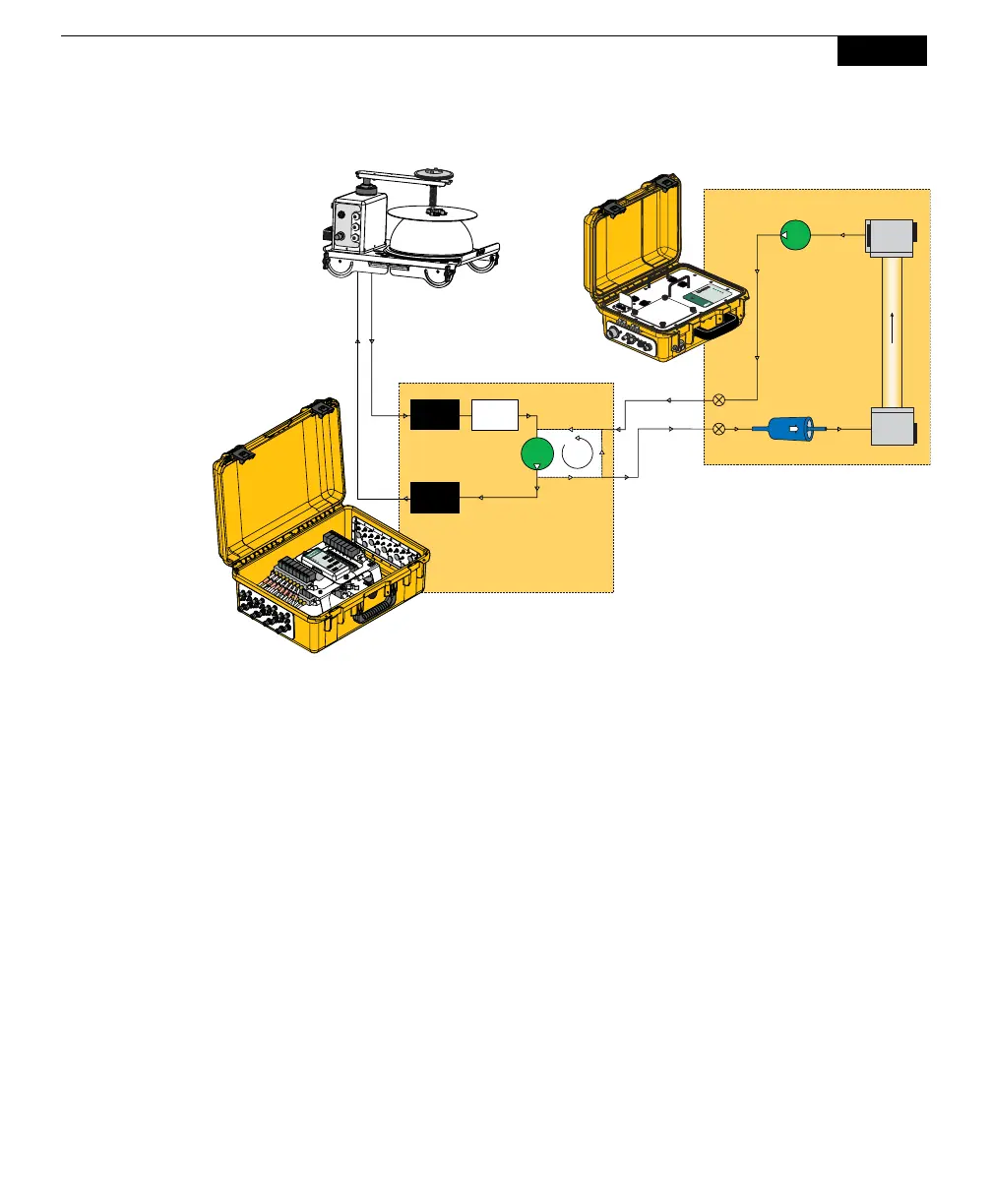
The above block diagram shows the direction of flow, and the major components
contained in the pneumatic circuit. Solenoid valves are used to control flow to and
from one chamber at a time (there is a separate valve for inlet and outlet). Thus,
the 8-port multiplexer has 16 solenoids, and the 16-port multiplexer has 32
solenoids. Sample gas from the chamber is filtered as it enters the pneumatic
circuit; it is filtered again in the LI-8100A before it is measured by the IRGA.
A diaphragm pump is used to circulate the sample gas to and from the multiplexer
and the selected chamber. A flow sensor measures the approximate flow rate in
the ‘chamber loop’ (between 1.5 and 3.5 lpm in normal operating conditions). The
flow rate is adjustable in software. The pump also circulates flow in a ‘sub-
sampling loop’, as it is in-line with both parallel loops. Flow restrictors in the ‘sub-
sampling loop’ restrict flow in comparison to the ‘chamber loop’ to control the
pressure in the LI-8100A IRGA. The LI-8100A, in turn, samples air from the ‘sub-
sampling loop’ using its own pump. The LI-8100A bellows pump circuit is used to
pressurize each chamber to test for leaks.


 To Next Page