User Manual Liebert Hipulse E Chapter 11 – ‘1+N System’
Single or '1+N' UPS System
(07/04) Page 11-3
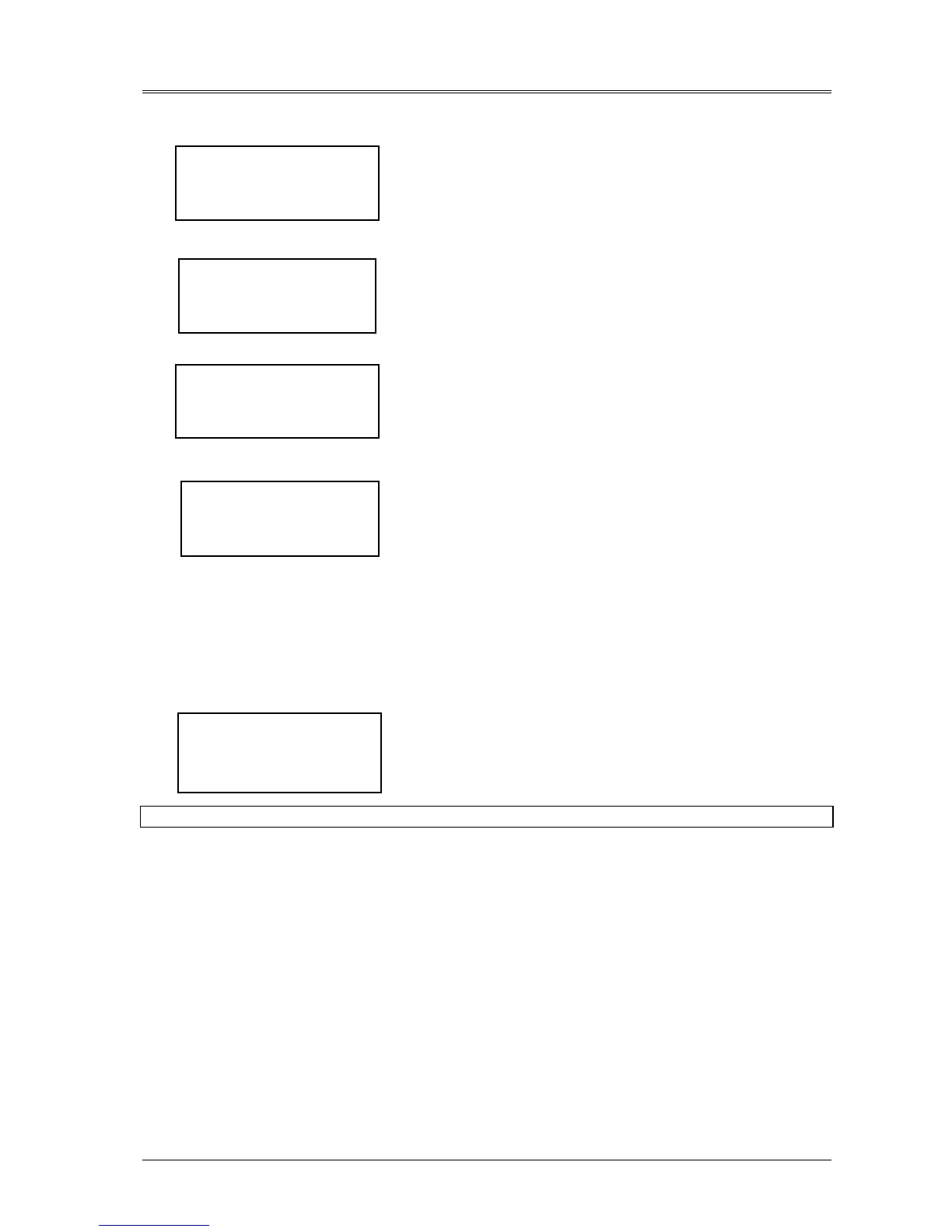
The Main Menu Window will display:
Select MEASUREMENT and press ENTER key:
Select MEASURES and press ENTER key.
Select BATTERY and the d.c. bus bar voltage will be displayed:
If the voltage indicated is satisfactory (432V d.c. for 380V a.c. system
446V d.c. for 400V a.c. system and 459V d.c for a 415V a.c. system)
press the escape key repeatedly until the display returns to the original
window.
5. Manually close the battery circuit breaker .
The Module Mimic indicator ( 3 ) Battery unavailable should extinguish. Several LED's on the Battery state of
charge bar graph ( 17 ) will illuminate showing the battery state of charge.
When the battery circuit breaker has been closed and the inverter has stabilized the screen will change to the
default window.
Default Window.
The message shown below, will be seen on the default screen whenever the UPS is operating normally:
The top lines display the UPS operational status and indicates alarm
conditions when they occur; and line four normally shows the time and
date.
The UPS is operating normally with its inverter supplying the load.
Follow the foregoing procedure for the others UPS.
For a system configured in the “1+N system”, the 'N' UPS modules will simultaneously change from “load on bypass”
to “load on inverter” provided that a sufficient number of modules are running, and on-line, to satisfy the power load
requirements.
BATTERY:
VOLTAGE 446 [V]
CURRENT 001 [A]
CHARGE 000 [%]
NORMAL OPERATION
HH.MM.SS DD.MM.YY
>MEASUR./ALARM HIST.<
FUNCTION
MAINTENANCE
SETUP
OUTPUT
INPUT
> BATTERY <
TEMPERATURE
>MEASURES<
ALARM HISTORY
RUNNING TIME