Chapter 11 – ‘1+N System’ Liebert Hipulse E User Manual
Single or '1+N' UPS System
Page 11-2 (07/04)
11.2 Operating Instruction
Starting and stopping the '1+N' system is the same as a single module, however the module' response depends on
whether it is configured on the menu of the Operator Control Panel.
11.2.1 System Start-Up and shutdown procedures
WARNING
If differential circuit breakers are used on UPS unit inputs, use a common device only on the system’s bypass mains.
At the instant of electrical connection, the current may not be split instantaneously and this may cause the residual
current circuit-breakers to trip separately.
These operations must be performed one at a time, progressing to the next step only after having completed the
previous step on both UPS modules.
11.2.1.1 System start-up
This procedure should be followed when turning on the UPS from a fully powered down condition - i.e. where the load
is not being initially supplied at all. It is assumed that the installation is complete, the system has been commissioned by
authorized personnel and the external power isolators are closed
1. Open the UPS door(s) to gain access to the main power switches.
WARNING
THE FOLLOWING ACTION WILL APPLY POWER TO THE LOAD EQUIPMENT - ENSURE THAT IT IS
SAFE TO DO SO.
2. Close the bypass power switch Q2.
The Module Mimic LED's will indicate Bypass supply healthy ( 1 - steady green ) and the Load on bypass ( 6 -
flashing amber ).
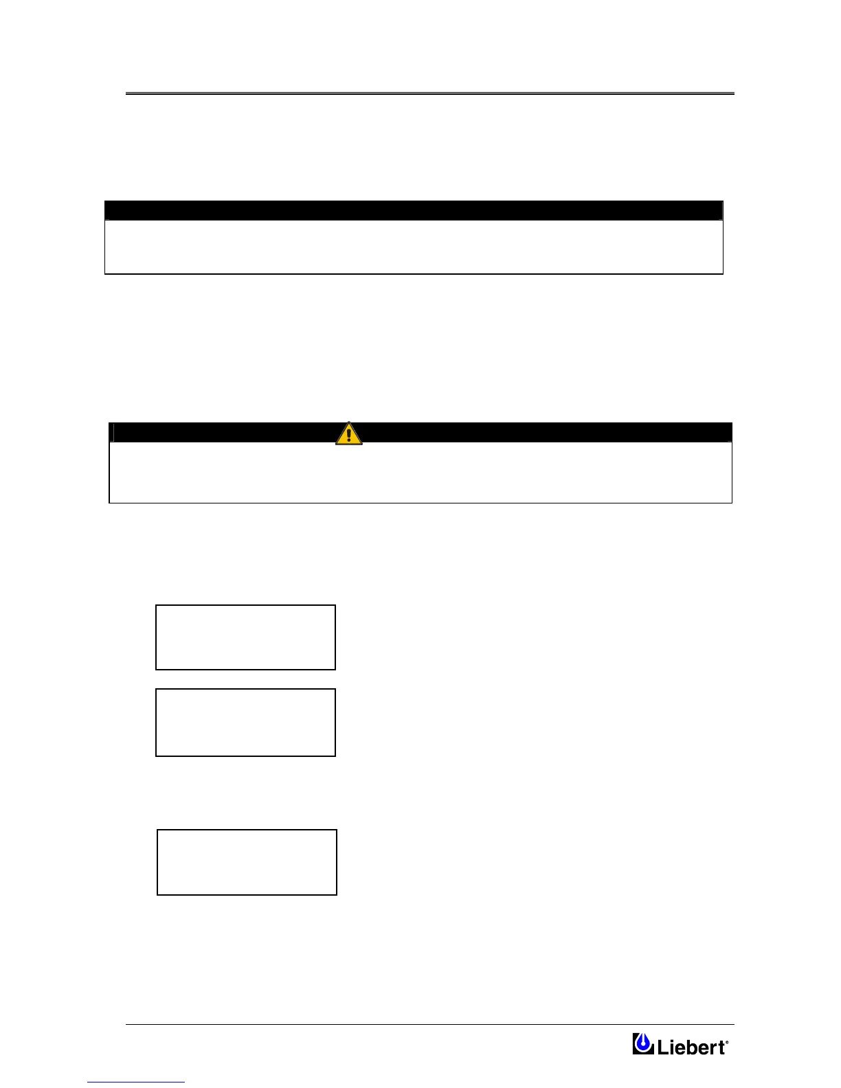
The Display screen will show the following:
Initializing Window: after first connecting power to the UPS and
closing the Q2 isolator, this message will appear on the LCD screen. It
persists for about five seconds while the control firmware is loaded. It is
followed by a screen showing various messages with the time and date
on the bottom line.
Note: If input power is present but the display remains blank, then the
Micro Controller is not working, please contact your dealer for advice.
3. Close the Rectifier input power switch Q1 the and UPS output power switch Q4
After approximately 20 seconds the Module Mimic LED's will change so that the Load on inverter will light
( 5 - steady green ) and the Load on bypass ( 6 ) will extinguish.
The display window will show:
4. Before closing the battery circuit breaker check the d.c. bus-bar voltage. From the above window press the
ENTER key:
LIEBERT
UPS
RECTIF. SWITCH OPEN
BATTERY C.B. OPEN
OUTPUT SWITCH OPEN
HH.MM.SS DD.MM.YY
BATTERY C.B. OPEN
HH.MM.S DD.MM.YY