Chapter 12 – Additional Equipment Liebert Hipulse E User Manual
Single or '1+N' UPS System
Page 12-4 (07/04)
12.3 UPS I\O AS400 Alarm Interface Board (P\N 4590055P)
This board has several functions as described below.
12.3.1 Remote Control Inputs (X5)
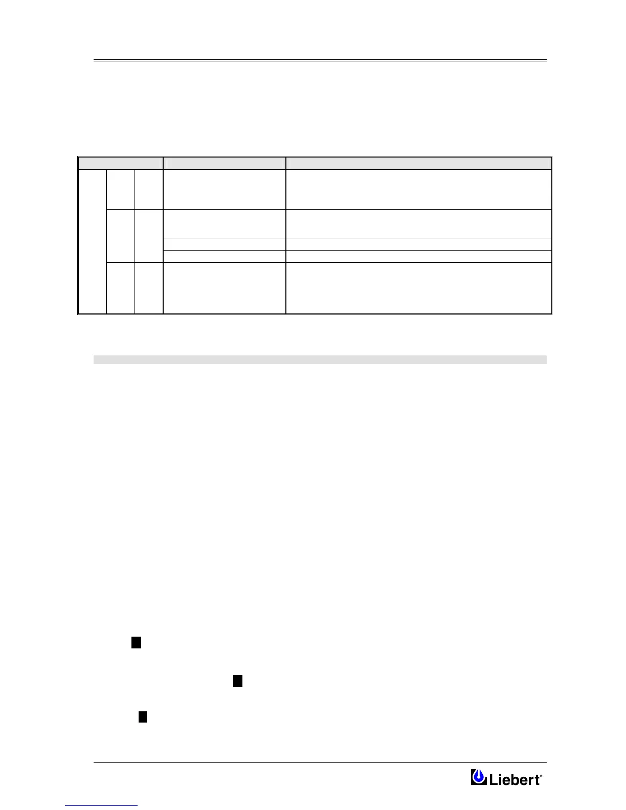
The Interface Board has facilities to accept three remote control inputs on terminal block (X5), as shown in figure 12-2.
The remote controls are:
Reference Definition Description
1-2
Battery ground fault
(Insert jumper on X6 2-3)
This input is used to enable the alarm on the UPS operator's panel both in
the event of insulation loss of the battery (if the battery ground fault
detection option has been installed).
Inverter Off
This remote input allows the inverter to be shut down (transferring the load
to the bypass supply ). See Note 3
Rectifier Off
This remote input allows the rectifier to be shut down. See Note 3
3-4
Static switch Off
This remote input allows the static switch to be shut down. See Note 3
X5
5-6
On generator
This remote input is most often used in conjunction with a stand-by
generator, which may be activated when the input mains supply fails.
The effects of this input can be configured from the Operator Control Panel
to a combination of the following: reduce the input current limit; reduce the
battery current limit; inhibit the inverter/bypass synchronisation .
The voltage applied to these terminals must be generated by an external power source and not taken from the UPS
internal low voltage supplies.
NOTE
1) Control is achieved by application of control signals ( 12V d.c. or a.c. ) to terminal block X5 as shown in figure 12-2.
2) Jumper X6 on 1-2 blocks the load on the inverter side, thus preventing the switching to the bypass mode (this
function is used for the LBS option).
3) Depending on customers' requirements, all three inputs or each of them can be used to enable the specific functions
described above. This can be done by selecting IN/OUT BOARD on the operator's panel. This window is protected by a
password that restricts the access of users to complex control functions, which are however accessible without limitations
to authorized servicing personnel. Always verify that all changes of original settings are recorded in the commissioning
documentation.
12.3.2 AS 400 Interface (X3)
The AS400 Alarm Interface Board connects the four most operationally critical UPS alarms to an IBM AS400 computer,
which is designed to monitor such alarms and respond to their appearance. Connection to the AS400 is provided on the
Alarm Interface Board via a terminal block X3. These alarm signals are provided by volt-free relay contacts, Maximum
contact rating is 50 Vdc @ 1A.
The alarms in question are:
• UPS Bypass
(RL-K6)
This warning message signals that the load is powered by the static bypass and is not protected by the distortion of the
mains supply. This signal is disabled if the 'ECOMODE' mode has been selected.
• Battery Low
(RL-K7)
This alarm is enabled only if the maintenance bypass switch is open, the load is “on-inverter”, and the rectifier is stopped
for any reason. The alarm then activates when the battery voltage falls below the minimum programmed Low Battery
Level.
• UPS ON 11 (RL-K8)
This warning message signals that the load is suppied by the UPS regardless of whether it is used as inverter or static
bypass. This signal is disabled if the load is set to the maintenance bypass.
• Utility Failure (Rectifier mains) 12 (RL-K9)
This alarm is enabled only if the maintenance bypass switch is open and the load is “on-inverter”. The alarm then activates
when the rectifier is stopped for any reason.
Common 13