User Manual Liebert Hipulse E Chapter 11 – ‘1+N System’
Single or '1+N' UPS System
(07/04) Page 11-11
11.2.6 SWITCHING THE SYSTEM ON FROM A MAINTENANCE POWER DOWN CONDITION.
This procedure will describe how to start the UPS and the how to transfer the load from the external maintenance
bypass to the UPS inverter. It is assumed that the installation is complete, the system has been commissioned by
authorized personnel and the external power isolators are closed. Study the reference drawings provided in figures
4-7 and 4-8. Refer to Fig. 9-1 for corresponding isolators Q1 to Q4.
Note: the procedure can be performed only if option Castell Interlock has been correctly installed. If the system is
not equipped with this option, skip the points that describe the operations related to Castell keys (i.e. points 1-8-11-
17-18).
ENSURE CORRECT PHASE ROTATION.
1. The Castell keys (BP1) will be located in the UPS. The other keys will located in the Key Exchange Box, and
in the external Maintenance Bypass switch.
2. Close external Maintenance Bypass switch (QBYP) (inside Maintenance Bypass cabinet).
3. Close the Output power switch Q4 and the Bypass power switch Q2.
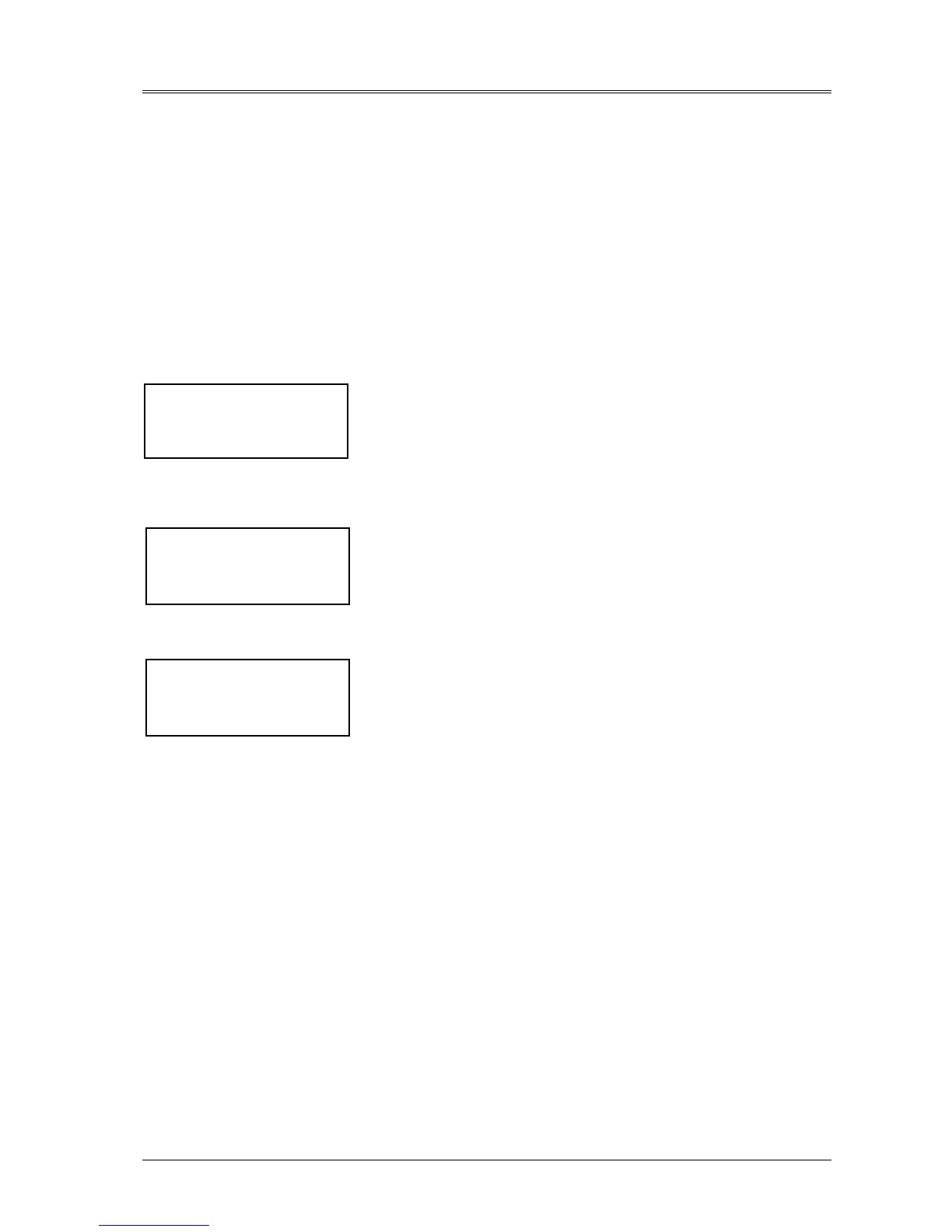
Initializing Window: after first connecting power to the UPS and closing
the isolator, this message will appear on the LCD screen. It persists for
about five seconds while the control firmware is loaded. It is followed by a
screen showing various messages with the time and date on the bottom line.
The Module Mimic indicators Bypass supply healthy ( 1 ) and after 20 seconds Load on bypass ( 6 ) will flash and red
led (13) will illuminate.
The Display window will show the present status of the UPS:
4. Close the Rectifier input power switch Q1.
5. Wait for 20 seconds then close the battery circuit breaker.
The Module Mimic indicator ( 3 ) Battery unavailable should extinguish. Several LED's on the Battery state of
charge bar graph will illuminate showing the battery state of charge.
The rectifier will `walk-in' and stabilize at float the voltage.
6. Repeat steps 1÷5 for the other UPS modules.
7. For UPS 1, using the display panel, turn the “Inverter Off”. The UPS display should indicate “Load on Bypass”,
and “Inverter Off via Display”.
8. Rotate and remove the Castell key from the UPS module.
9. Insert and rotate it in the Key Exchange Box. The key, which is fixed in position by means of a mechanical device,
can only be removed by pressing the energising button of the solenoid and when the green indicator is on. (only for
electric Castell Interlock).
10. Repeat steps 7 and 9 for all the other UPS modules.
11. With all the UPS keys (BP1) located in the Key Exchange Box, remove the trapped key (BP2), insert and rotate it in
the external UPS Switch.
RECTIF. SWITCH OPEN
BATTERY C.B. OPEN
MANUAL BYPASS CLOSED
HH.MM.SS DD.MM.YY
LOAD ON BYPASS
MANUAL BYPASS CLOSED
INV OFF
HH.MM.SS DD.MM.YY
LIEBERT
UPS