Chapter 2 - Installation Procedure Liebert Hipulse E Installation Manual
Installation (Electrical) Single or '1+N' UPS System
Page 2-12 (07/04)
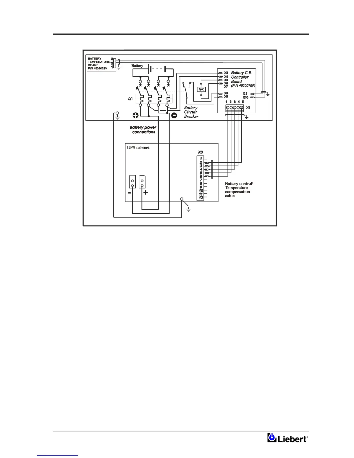
Figure 2-2 Battery Connection
2.3.3 Emergency Stop
If an external Emergency Stop facility is required it is connected to terminals 5 & 6 of the Auxiliary Terminal Block
(X4) and connected to the `normally closed' remote stop switch between these two terminals using shielded cable. If
this facility is not used then terminals 5 & 6 must be linked-out as shown in Figure 2-1.
Note 1
The Emergency Stop action within the UPS shuts down the rectifier, inverter and static bypass and
trips the battery circuit breaker. It does not however internally disconnect the input mains supply. If
required, this additional action can be facilitated by feeding the UPS input via an isolator which can
be tripped by a second contact of the Emergency Stop switch.
Note 2
Terminals 11 & 12 of the Auxiliary Terminal Block(X4) are connected to a «normally closed» contact
of the UPS Display Panel emergency Stop button and go open circuit when the button is pressed. This
output can be used as part of a wider Emergency Stop system to initiate an external action (such as
tripping an external supply breaker).