Chapter 2 - Installation Procedure Liebert Hipulse E Installation Manual
Installation (Electrical) Single or '1+N' UPS System
Page 2-2 (07/04)
2.1.2 Table for determining power cable size
The table below gives nominal currents for determining the size of UPS power cables. Other factors, which must be
taken into consideration include cable route length, coordination with protective devices, etc.
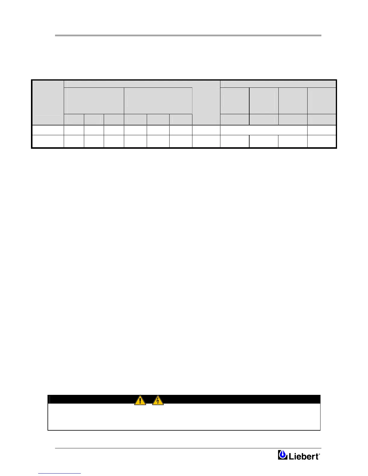
The power cables can be sized to suit the UPS module rating according to the table below:
NOMINAL CURRENT: Amps BUSBAR STUD SIZE
Input Mains
with full battery recharge
(subtract 5% for 12-
pulse)
Bypass\Output
at full load
Input/
Cables
Bypass/
Output
Cables
Battery
Cables
Torque
Load
(Nm)
UPS
RATING
(kVA)
380V 400V 415V 380V 400V 415V
Battery at
minimum
battery
voltage
(400Vac)
*
300
632 600 578 470 446 430 775
M12 (Bolt) Ø13 (holes)
45
400
842 800 771 627 595 574 1030 M12 Ø13 M10 Ø11 M12 Ø13
45 (M12)
26 (M10)
Table 2-1 UPS Module cabinet power cable rating
*Maximum battery discharge current at 380VAC supply increase by 3%, and for a 415VAC supply decrease by 3%
2.1.3 General Notes
The following are guidelines only and superseded by local regulations and codes of practice where applicable:
1. Take special care when determining the size of the neutral cable, as current circulating on the neutral cable may be
greater than nominal current in the case of non-linear loads. Refer to the values given in the ‘UPS Electrical
characteristics’ table in Chapter 5.
2. The earth conductor should be sized according to the fault rating, cable lengths, type of protection, etc. The earth
cable connecting the UPS to the main ground system must follow the most direct route possible.
3. Consideration should be given to the use of paralleled smaller cables for heavy currents, as this can ease installation
considerably.
4. When sizing battery cables, a maximum volt drop of 3Vd.c. is permissible at the current ratings given in Table 2-1.
5. In most installations, especially those concerning parallel multi-module systems, the load equipment is connected to
a distribution network of individually protected busbars fed by the UPS output rather than being connected directly
to the UPS itself. Where this is the case the UPS output cables can be rated to suit the individual distribution
network demands rather than being fully load-rated.
6. When laying the power cables, do not form coils, so as to avoid increasing formation of electromagnetic
interference.
7. In parallel multi-module systems, the output cable of each unit should be kept as equi-distant as possible between
the unit output terminals and the parallel distribution busbar to prevent from affecting the shared current.
2.1.4 Cable connections
The rectifier input, bypass, output and battery power cables ( all require lug type terminations ) are connected to
busbars situated below the power isolator switches - as shown in Chapter 6. These are accessible when the power
compartment cover plate is removed.
A terminal block X3 is used for connecting the control cables to the battery circuit breaker and a second terminal block
X4 is used for the external emergency stop facility, external OFF inverter, ext. Bypass, etc. these are female spade type
connections ( Fast-on 6,3 x 0,8 ) and are described later in Section 2.3.
2.1.5 Safety earth
The safety earth bus-bar is located near the input and output power supply connections as shown in Chapter 6. The
safety earth cable must be connected to the earth bus-bar and bonded to each cabinet in the system.
All cabinets and cable trunking should be earthed in accordance with local regulations.
Note: Proper grounding considerably reduces problems in systems caused by electromagnetic interference.
WARNING
FAILURE TO FOLLOW ADEQUATE EARTHING PROCEDURES CAN RESULT IN ELECTRIC SHOCK
HAZARD TO PERSONNEL, OR THE RISK OF FIRE, SHOULD AN EARTH FAULT OCCUR.