Chapter 5 – ‘Specification’ Liebert Hipulse E Installation Manual
Single or '1+N' UPS System
Page 5-4 (07/04)
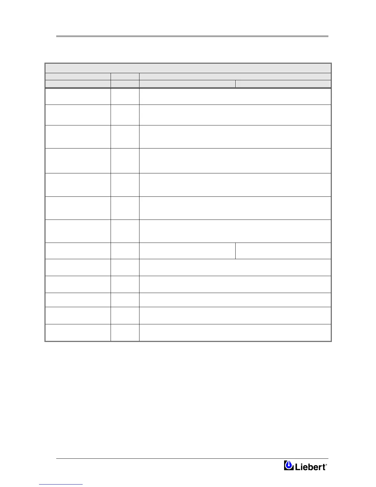
5.5 UPS Electrical Characteristics (DC Intermediate Circuit)
DC INTERMEDIATE CIRCUIT
UNITS
Rated power kVA 300 400
Voltage range for inverter
operation
Vdc 320 – 490
Recommended number of
lead-acid cells
-
No
192 ( 380Va.c.)
198 ( 400Va.c.)
204 ( 415Va.c.)
Recommended float
charge voltage
2.25 V/el.
Vdc
432 ( 380Va.c.)
446 ( 400Va.c.)
459 ( 415Va.c.)
Recommended boost
charge voltage
2.40 V/el.
Vdc
460 ( 380Va.c.)
475 ( 400Va.c.)
490 ( 415Va.c.)
Recommended end of
discharge voltage
1.67 V/el.
Vdc
320 ( 380Va.c.)
330 ( 400Va.c.)
340 ( 415Va.c.)
Recommended test
voltage
1.90 V/el.
Vdc
365 ( 380Va.c.)
376 ( 400Va.c.)
388 ( 415Va.c.)
Maximum voltage on
manual charge
2.45 V/el.
Vdc
480 ( 380Va.c.)
495 ( 400Va.c.)
500 ( 415Va.c.)
Maximum recharge
battery current
A 150 200
Battery boost charge cycle
-
Characteristics to DIN 41772 I-U, boost to floating charge switching, with current
measuring criterion plus control of charging time
Maximum boost charge
duration
min 0-999
Boost-float threshold current
A 0-99
Temperature voltage
compensation
mV/°C 2
Ripple voltage
superimposed
%
≤1
Note:
= (According to rated voltage).
= Factory set for rated 400 V, different cells number and voltage per cell may be set by software and/or trimmers on
Rectifier Control Board.
= Set by software.
= With external temperature sensor, feature selected on Rectifier Control Board.
= Battery disconnected, RMS percentage value referred to DC voltage.
= Lead acid (SMF/VRLA and WET cell) and Ni-Cad with constant voltage and current charging for European units.