User Manual Liebert Hipulse E Chapter 12 – Additional Equipment
Single or '1+N' UPS System
(07/04) Page 12-11
12.10 RS232 communications
This section gives a brief outline of external communication options available for the Liebert Hipulse E UPS.
12.10.1 RS232 communication kit
It is possible to implement local or remote RS-232 communications between the Liebert Hipulse E UPS system and a
Personal Computer (PC) using a purpose-designed communications kit.
An RS232 (X8) connector is fitted on the Operator Logic Board as standard on all UPS systems to allow remote
interfacing of the UPS front panel control and indication functions.
The optional RS232 communication kit allows to transfer some information available from the UPS display system and
converts it into a customer-usable form for local or remote display.
When installed, the communications kit enables the following functions to be carried out from the PC terminal:
• Set and modify the UPS system parameters.
• Monitor the UPS alarms status, and provide an alarms history if required.
• Monitor system analogue parameters (voltage, current, frequency, power, temperature).
• Activate UPS commands (set date/time, ON-OFF of rectifier / inverter / bypass, etc.).
• Detect UPS communications set-up (node configuration).
Local operation is achieved by connecting a personal computer (PC) directly to the UPS module via an RS-232 cable of
up to 15m length. For communication over greater distances a pair of modems are required to provide the necessary
interface with the Public Telephone Service Network (PTSN).
The UPS control system is ready-prepared for external communications via connectors X9 and X8 on its Operator
Logic Board (located back on the front door): connector X9 and X8 provide an RS-232 Interface.
The hardware includes a male connector fixed on the aluminium panel fitted to the lower left-hand region of the
module (under the auxiliary terminal block) which is connected to the Operator Logic Board (via X8). The output
connector (X9 on the aluminium panel) is then connected to the PC for a local installation or to a modem in a remote
installation. The X9 connector is a 25 pin D-type male connector (D-25) with a standard RS-232 pin out.
12.10.2 Modem
Using a modem, Liebert Hipulse E is able to transmit the status of the UPS to a remote location over a telephone line.
For this purpose, space has been left on the inner side of the UPS door. The modem should be connected to the RS232
(X8) on the Operator Logic Board. The modem power supply may be derived from the 250Vac max supply inside the
UPS (the power cable should be supplied with modem). The telephone line should be secured in the cable passage
shown in the figure in Chapter 6.
12.10.3 Communication kit – installation with several modules
It is possible to use the communications kit to monitor and control up to eight UPS modules. Such modules may be
configured as independent Single module systems, 1+N systems, or Multimodule.
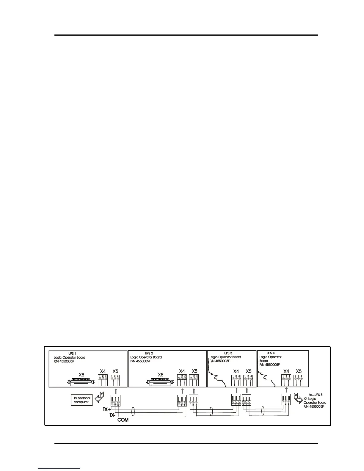
From a hardware viewpoint, when two (or more) modules are connected to the communications system only one
module is connected to the PC/Modem via the Communications Interface Board - this is classed as the master module.
The remaining modules, which are classified as slave modules, are daisy-chained to the master module via an 3 poles
connector X4 input and X5 output of the Operator Logic Board, as shown figure below, thus the control and
operational data for each module is transmitted through the communication link to the P.C. via the master module. Note
that the connectors (X4&5) are the female 3-pin.
Figure 12-5 – RS485 connections