User Manual Liebert Hipulse E Chapter 12 – Additional Equipment
Single or '1+N' UPS System
(07/04) Page 12-7
12.4 UPS Extension Alarm Interface Board (P\N 4590056Q)
This board is connected (piggy back style) directly via connector X1 onto the Interface Board connector X2 of
4590055P as shown in figure 12-1. This board can only be used in conjunction with the Interface Board (4590055 P).
12.4.1 Standard Alarm Outputs
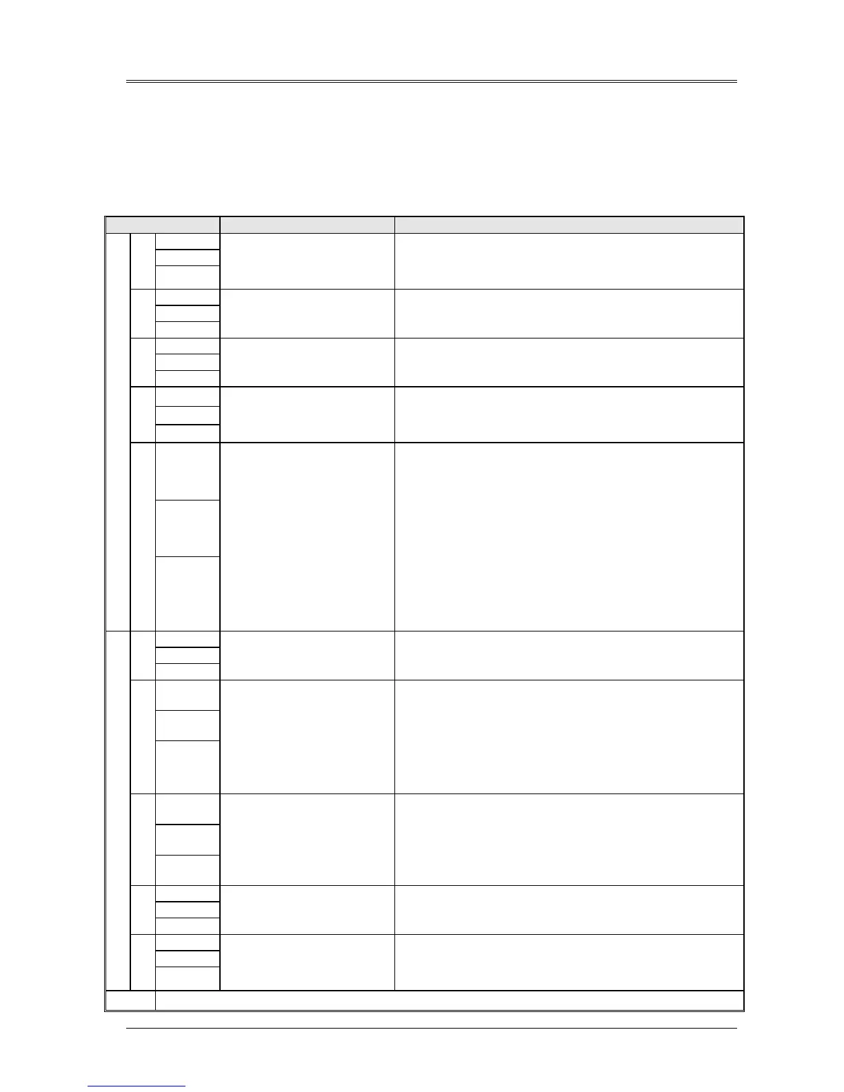
The Extension Alarm Interface board contains a number of relays driven by alarm signals generated within the UPS, whose
contacts provide a set of volt-free alarm outputs that are connected to terminal blocks X2 and X3 as shown in figure 12-3.
These outputs can be used to drive an external alarms monitoring device.
Reference Definition Description
15 NO
14 COM
RL
K1
13 NC
BATTERY ON LOAD
This message informs the operator that the load is supplied from the
battery system and the battery is discharging.
This alarm is enabled when the battery breaker is closed and the battery
fuse in intact and then active when rectifier block signal is present.
12 NO
11 COM
RL
K2
10 NC
OVERLOAD
This message informs the operator that the load exceed 150% of the UPS
rating, and the load will transfer to bypass some time later depending on
the degree of overload present.
9 NO
8 COM
RL
K3
7 NC
INVERTER
OVERTEMPERATURE
This alarm is active when an output transformer overtemperature or an
inverter overtemperature is enabled (thermostat on heatsink is
intervened).
6 NO
5 COM
RL
K4
4 NC
INVERTER
UNSYNCHRONISED
This warns that the inverter is not synchronised with the bypass supply,
which is normally due to a problem with the bypass supply being outside
an acceptable frequency window. In 1+N parallel system one (or more)
UPS is not synchronised with other modules or with bypass supply.
3 NO
2 COM
X2
RL
K5
1 NC
COMMON ALARM
This is a general alarm facility and is activated from any of the following:
• Rectifier blocked.
• Battery c.b. open, battery fuse fail, DC bus undervoltage.
• Inverter is unsynchronized.
• INV: Overtemperature is active.
• OUT: undervoltage/ no voltage, wave form error.
• Inverter: OFF, blocked, INV: current limit, undervoltage.
Additional alarms for 1+N configuration:
• Bypass-side static switch is blocked (inhibited) by hardware.
• Bypass supply failure.
• Bypass OFF/ overvoltage/ undervoltage
• Maintenance Bypass isolator is closed
• Number inverters not OK
15 NO
14 COM
RL
K6
13 NC
FAN FAILURE ALARM
This message informs the operator that there is a failure in the outgoing
air ventilation system (with option included).
12 NO
11 COM
RL
K7
10 NC
TRANSFER ON BYPASS
INHIBIT
This alarm is activated from any of the following:
• the bypass has been inhibit by the operator from either the front
panel display or an external PC.
• one or more of the UPS static switch SCR’s has developed a fault.
• input ac supply failed or out of specified acceptable range.
• bypass switch open.
This alarm is valid only for UPS units in single configuration and not for
the ‘1+N’ configuration.
9 NO
8 COM
RL
K8
7 NC
RECTIFIER/MAINS
FAILURE
This message informs the operator that the rectifier is not producing its
correct output voltage; this can be caused by:
an operator selection to OFF, input rectifier ac supply failed or out of
specified acceptable range, rectifier switch open or an internal fault.
6 NO
5 COM
RL
K9
4 NC
BACK FEED FAULT
This message informs the operator that failure of the Bypass static
devices has resulted in voltage being fed back to the bypass supply
input.
3 NO
2 COM
X3
RL
K
10
1 NC
BATTERY C.B. OPEN
The battery circuit breaker is open. Note that if the mains power fails
then the UPS output will also fail together with load power, since the
inverter has no battery back-up. Verify that the jumper is setting on X4
1-2.
X1
Connect piggy-back to X2 of Alarm Interface Board (P\N 4590055P)