Chapter 8- Operating Instructions Liebert Hipulse E User Manual
Single or '1+N' UPS System Operator Control and Display Panel
Page 8-2 (07/04)
8.1.1 Operator control panel
The control and display panel LED indications are illustrated in figure 8-2 and described in the following text:
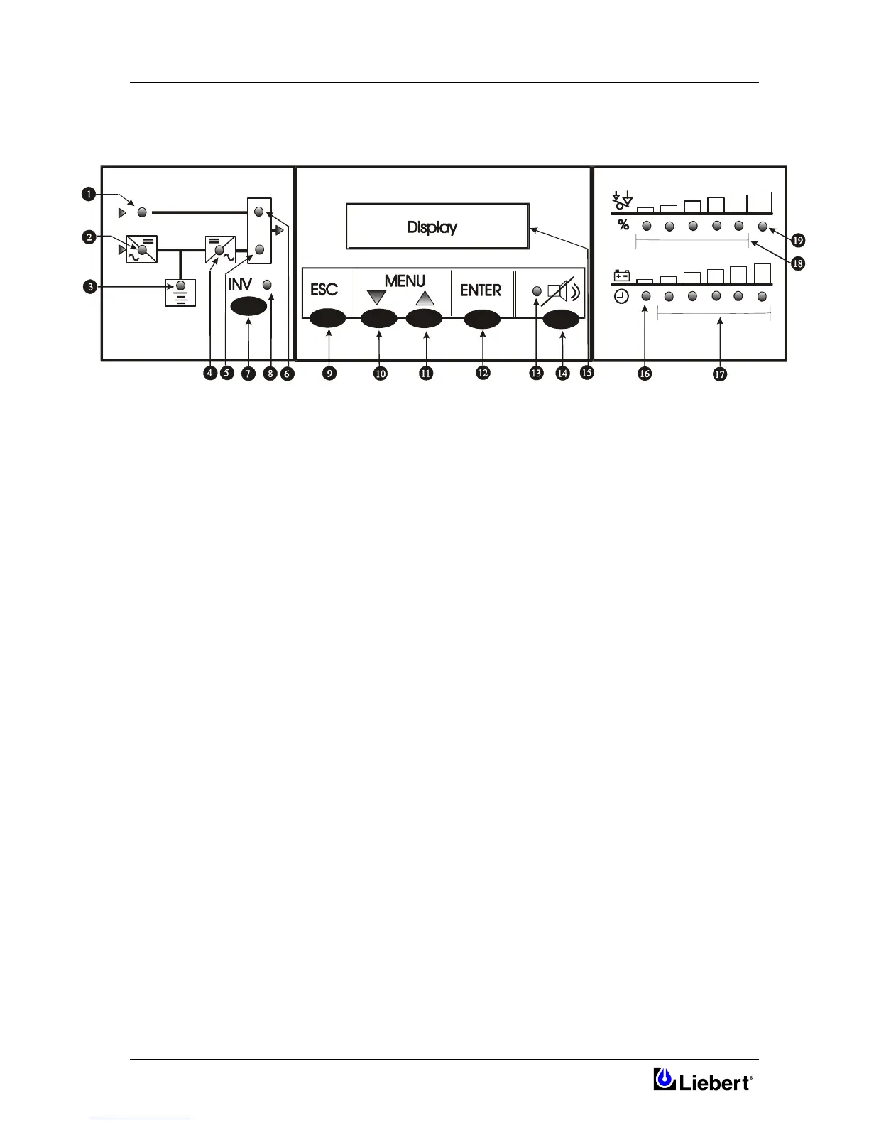
Figure 8-2 Single module operator control panel
Mimic indications
Six LED’s mounted on a single line diagram represent the various UPS power paths and show the current UPS
operational status:
1 Bypass supply healthy
This led illuminates when the bypass a.c. input power switch is closed and the input supply is within of set
value nominal voltage ( default ±10% ).
2 Input supply healthy and Rectifier is operative.
3 Battery status healthy.
This LED illuminates when the battery is discharging and flashes when the battery circuit breaker is open.
4 Inverter output healthy.
5 Load on Inverter status.
This led illuminates when the output power switch is closed and the load is connected to the inverter
6 Load on Bypass status.
This led illuminates when the output power switch is closed and the load is connected to the bypass a.c. supply
via the static switch.
Inverter control switch
7 Inverter ON — Manual inverter selection switch.
8 Inverter LED — inverter status indicator contained above the switch icon.
The Inverter Led (yellow) indicates when the Inverter is switched OFF.