Chapter 7 - General Description Liebert Hipulse E User Manual
Design Concept Single or '1+N' UPS System
Page 7-2 (07/04)
During normal operation both the rectifier and inverter sections are active and provide regulated load power whilst
simultaneously float charging the battery. In the event of a mains power failure, the rectifier becomes inoperative and
the inverter is powered solely from the battery. Critical load power is maintained under these conditions until the
battery is fully discharged, whereupon the UPS shuts down. The end of battery discharge is assumed when the battery
voltage falls below a preset value (i.e. 330V d.c. for a 400V a.c. system).
The period for which the load can be maintained following a mains power failure is known as the system's ‘Autonomy
Time' and is dependent upon both the battery A/Hr capacity and the applied percentage load.
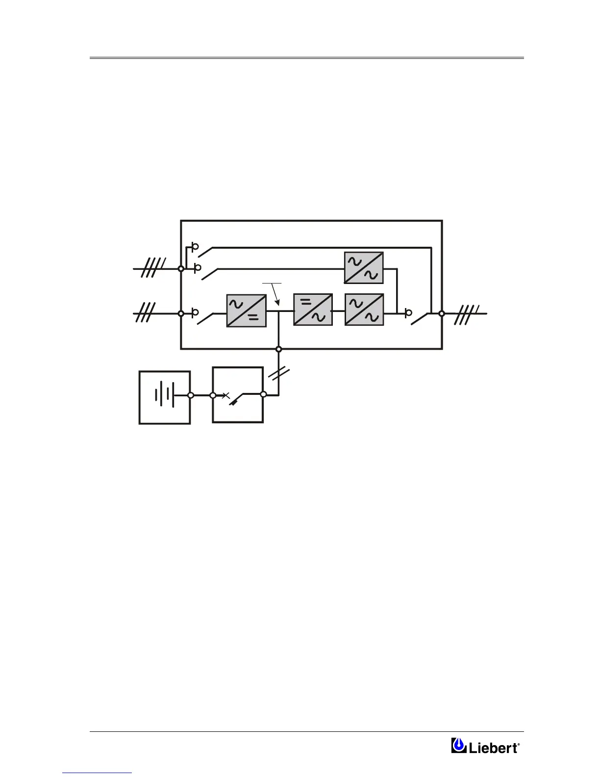
7.2.2 Bypass supplies
The circuit block annotated ‘Static Switch' in figure 7-2 contains an electronically controlled switching circuit which
enables the critical load to be connected either to the inverter output or to a bypass power source via the `static bypass
line'. During normal system operation the load is connected to the inverter and the 'inverter-side' of the Static Switch is
closed; but in the event of a UPS overload, or inverter failure, it is automatically transferred to the static bypass line.
Figure 7-2 UPS power switches configuration
To provide a clean ( no-break ) load transfer between the inverter output and static bypass line, the static switch
activates connecting the load to the bypass supplies. To achieve this, the inverter output and bypass supply must be
fully synchronized during normal operating conditions. This is achieved through the inverter control electronics which
make the inverter frequency track that of the static bypass supply provided that the bypass remains within an acceptable
frequency window. The synchronizing window is pre-selected to 2% of nominal frequency, giving an acceptable
frequency window ±1 Hz.
A manually controlled, `maintenance bypass' supply is also incorporated into the UPS design. Its purpose is to enable
the critical load to be powered from the mains ( bypass ) supply while the UPS is shut down for routine maintenance.
Note: The load equipment is not protected from normal supply aberrations when operating on Bypass side or in the
maintenance bypass mode
DC Bus
RECTIFIER
Bypass Isolator Q2
Maintenance Bypass Isolator Q3
Input
Isolator Q1
Output
Isolator Q4
Input
Mains
Supply
Bypass
Mains
Supply
UPS
Output
Battery
Bypass Side
INVERTER STATIC SWITCH
UPS MODULE
C.B.
Battery Circuit
Breaker