User Manual Liebert Hipulse E Chapter 7 - General Description
Single or '1+N' UPS System Design Concept
(07/04) Page 7-1
Part II – User Manual
7 Chapter 7 - General Description
7.1 Introduction
The Liebert Hipulse E Uninterruptible Power Supply (UPS) System is connected between a critical load, such as a
computer, and its three phase mains power supply. Being designed to furnish a well regulated 3 phase output power
supply under all rated load and input supply conditions, the system offers the user the following advantages:
Increased power quality:
The UPS has its own internal voltage and frequency regulators which ensure that its output is maintained within close
tolerances independent of voltage and frequency variations on the mains power lines.
Increased noise rejection:
By rectifying the input a.c. power to d.c. power, and then converting it back to a.c., any electrical noise present on the
input mains supply line is effectively isolated from the UPS output, therefore the critical load sees only clean power.
Power blackout protection:
If the mains power fails, the UPS continues to power the critical load from its battery source, leaving the load immune
from power disturbances.
7.2 Design Concept
7.2.1 Introduction
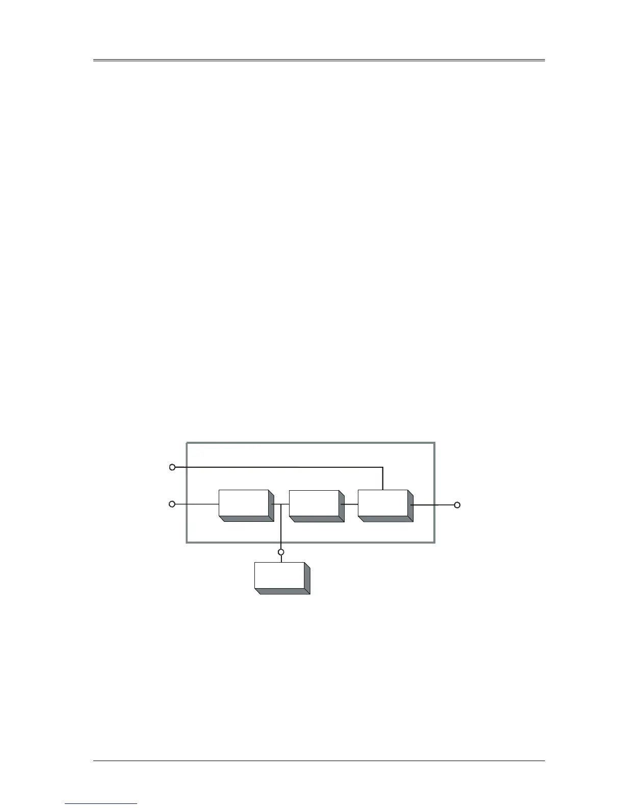
This section describes an individual module's operating principles. The UPS basically operates as an a.c. -d.c. -a.c.
converter (see figure 7-1). The first conversion stage (from a.c. to d.c.) uses a 3 phase, fully-controlled SCR bridge
rectifier to convert the incoming mains supply into a regulated d.c. bus-bar.
Figure 7-1 Single Module block diagram
The d.c. bus-bar produced by the rectifier provides both battery charging power - being equipped with a temperature
compensated battery charging system, to prolong battery life - and power to the inverter section – which utilizes the
latest IGBT switching pulse width modulation ( PWM ) design - and provides the second conversion phase, i.e.
reconverting the d.c. bus-bar voltage back into an a.c. voltage waveform.
UPS
Output
a.c.
Bypass
a.c.
Supply
Rectifier
a.c.
Supply
RECTIFIER
INVERTER
ST