Installation Manual Liebert Hipulse E Chapter 2 - Installation Procedure
Single or '1+N' UPS System Installation (Electrical)
(07/04) Page 2-11
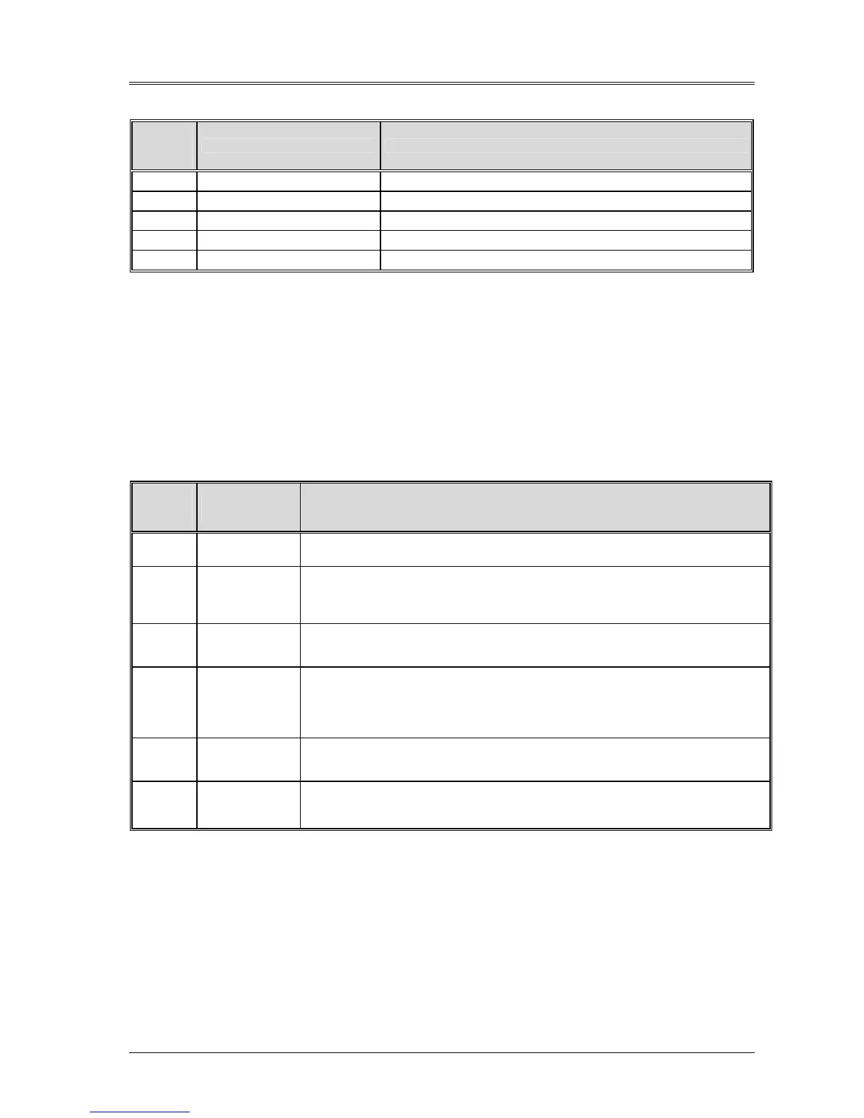
Auxiliary terminal block X3 at UPS.
X3
terminal
reference
Reference label Description
2 Common Temperature sensor common (0V)
3 T Batt. Temperature sensor signal
4 Common Common (0V)
5 Batt. Sw Battery Circuit Breaker open
6 Bat Trp Battery Circuit Breaker trip control
Table 2-3
Note: The auxiliary cables of the battery must be screened and double insulated.
The screen is connected to the earth of the battery circuit breaker cabinet or supporting rack.
Use multiple-core shielded cables with a section of 0.5 to 1 mm
2
.
Connect the cables with the Fast-on 6.3x 0.8 mm terminals (female).
2.3.2
Auxiliary terminal block X4
Next to terminal board X3 there is a second terminal board which may be used for auxiliary connection of equipment or
devices external to the UPS. Use the following table to identify the terminals corresponding to the equipment or device
to be connected.
Auxiliary terminal block X4 at UPS.
X4
terminal
reference
Reference
label
Description
1-2 Ext. OFF Inv
Remotely provides control for switching off the inverter.
The external contact employed must be normally open with the input switch open.
3-4 Ext. Sw Out
Indication to be provided at the UPS to note the opening of an external module output
isolator.
The external contact employed must be normally open with the output switch open.
If unused, leave the standard connectors in place.
5-6 Ext. EPO
Remotely provides control for switching off the UPS using a remote emergency button.
Normally closed contact.
If unused, leave the standard connectors in place.
7-8 Ext. BYP
Indication to be provided at the UPS to note the opening of an external maintenance bypass
switch.
The external contact employed must be normally closed with the external maintenance
bypass switch open.
If unused, leave the standard connectors in place.
9-10 Back Feed
Signal from the UPS to indicate a return flow of energy in the bypass mains.
The contact employed is normally open; if it is closed, this means a failure has been detected.
Refer to point 2.3.4 on the next page.
11-12 Int EPO
One contact is available for opening an external EPO switch assembled upstream of the UPS.
The normally closed contact is opened when the internal emergency button is pressed.
See Note 2 on the next page.
Table 2-4
Note: All auxiliary cables of terminal block X4 must be double insulated.
The cross-sectional area of the auxiliary cables is from 0.5 to 1 mm
2
.
Connect the cables with the Fast-on 6.3x 0.8 mm terminals (female).
Maximum contact rating on auxiliary terminals: 50 Vdc @ 1 Amp.