L-DALI User Manual 26 LOYTEC
Version 5.2 LOYTEC electronics GmbH
1. Check that the DALI LEDs (“DALI x ACT”, where x is 1 to 4) do not light up red. If
one of these LEDs is red, check the proper connection of the bus power supply for the
corresponding channel and check the DALI wiring for short-circuits.
2. Press the DALI mode button (“ON/OFF/AUTO”) on the front panel of the L-DALI
once. Now all DALI ballasts should be switched on (maximum level) and the DALI
LEDs on the L-DALI should light up green.
3. Press the DALI mode button again. Now all DALI ballasts should be switched off and
the DALI LEDs on the L-DALI should light up orange.
4. Press the DALI mode button again. This should not change the state of the DALI
ballasts but return the L-DALI to the auto-mode (control via CEA-709/BACnet
interface).
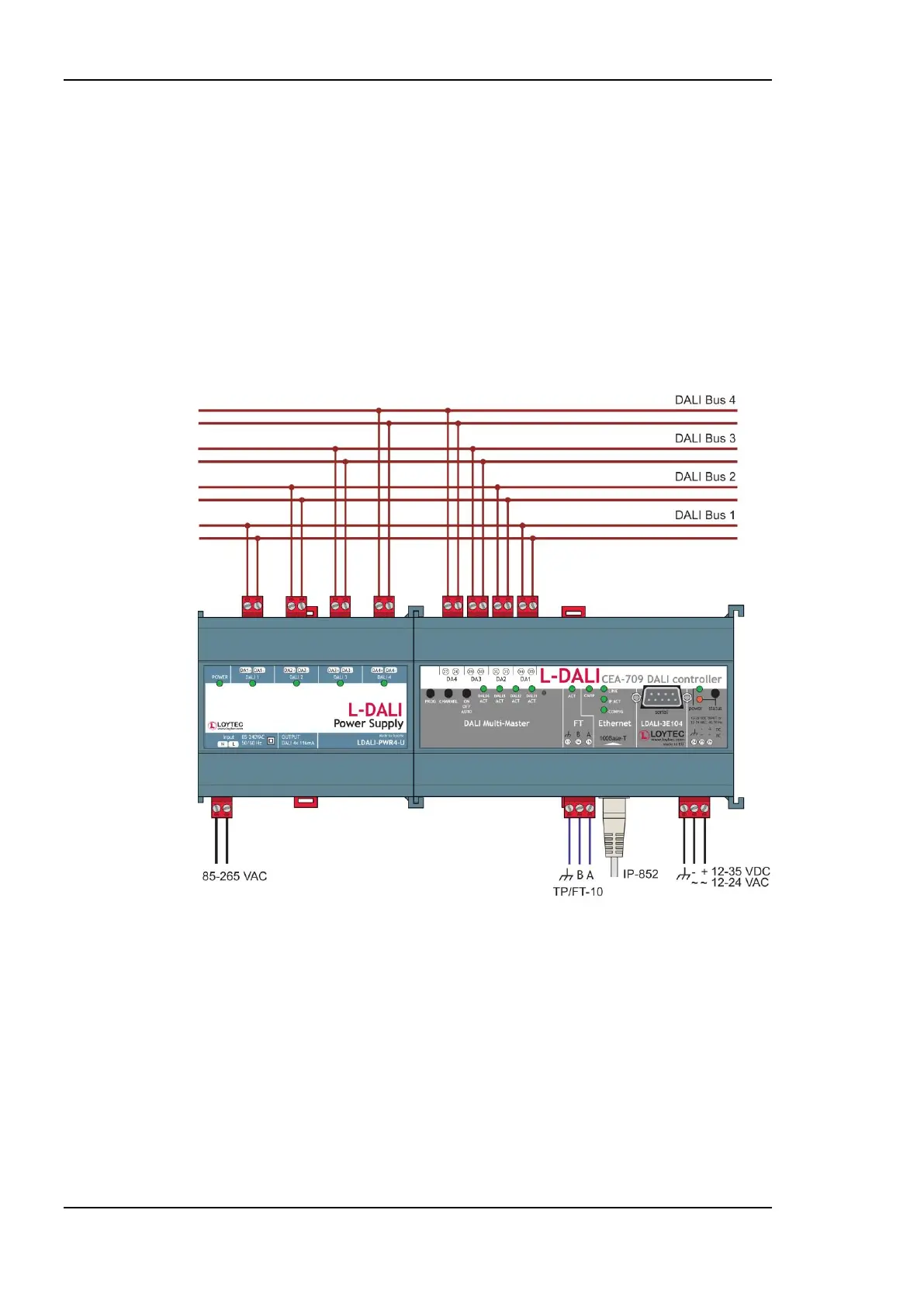
Figure 5: Basic Hardware Installation with external DALI bus power.
3.1.2 Models with built-in DALI Bus Power Supply
Connect the L-DALI to the power and to the DALI network as shown in Figure 5. To allow
for easy configuration it is recommended to always connect the L-DALI to the Ethernet
network (if available). More detailed instructions are given in Chapter 4.
After the DALI ballasts have been installed and connected to the DALI network, the
installation can be tested by following these steps:
1. Check that the status LED (“status”) does not light up red. If the LED is red, check the
DALI wiring for short-circuits.