L-DALI User Manual 64 LOYTEC
Version 5.2 LOYTEC electronics GmbH
foreign device behind a NAT router, port forwarding to the BACnet/IP port (UDP,
default port 0xBAC0) and optionally to the Web server and FTP server port (TCP,
default port 80 and 21) must be setup in the NAT router. If foreign device is selected,
the following, additional settings must be made:
o FD BBMD IP address and FD BBMD port: IP address and port of the
remote BBMD the device registers at as a foreign device.
o FD re-registration: A foreign device must periodically re-register at a
BBMD. Here you can setup the corresponding interval. The default is 1800
seconds.
o FD retry timeout and FD retries: Here you can specify the behavior, if
registration does not work instantly. These values should be left at default:
30000ms / 3 retries.
5.2.7 VNC Configuration
LOYTEC devices equipped with an LCD display also provide remote access over Ethernet
to the LCD display. The VNC protocol is used for this purpose and the device implements a
VNC server for exposing the display. The VNC server is by default disabled on the device.
On the PC a VNC client needs to be installed. Using the default settings, the VNC client
connects to port 5900 of the device. The password is ‘loytec4u’.
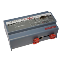
Figure 53: VNC Configuration.
The VNC server can be configured on the Ethernet tab of the port configuration. To turn
on the VNC server, enable the VNC for LCD UI checkbox. The VNC protocol settings are
displayed in the settings box on the right-hand side as shown in Figure 53. The VNC port
and VNC password can be changed. As a default, only one VNC client may connect. This
limit may be increased in Max VNC clients. In order to protect changes made on the LCD
UI over VNC with a PIN code, the Admin PIN code can be configured. To disable PIN
protection, enter ‘0000’.
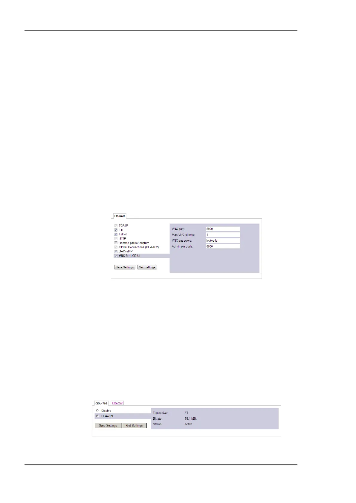
5.2.8 CEA-709 Configuration (LDALI-10X only)
The CEA-709 protocol can be enabled/disabled as shown in Figure 54. The protocol
settings box on the right-hand side displays the current transceiver settings. Note, that
enabling the CEA-709 protocol will disable the CEA-852 protocol and vice versa.
Figure 54: CEA-709 Configuration Page.