L-DALI User Manual 25 LOYTEC
Version 5.2 LOYTEC electronics GmbH
3 Quick-Start Guide
This Chapter contains step-by-step instructions on how to configure the L-DALI for the
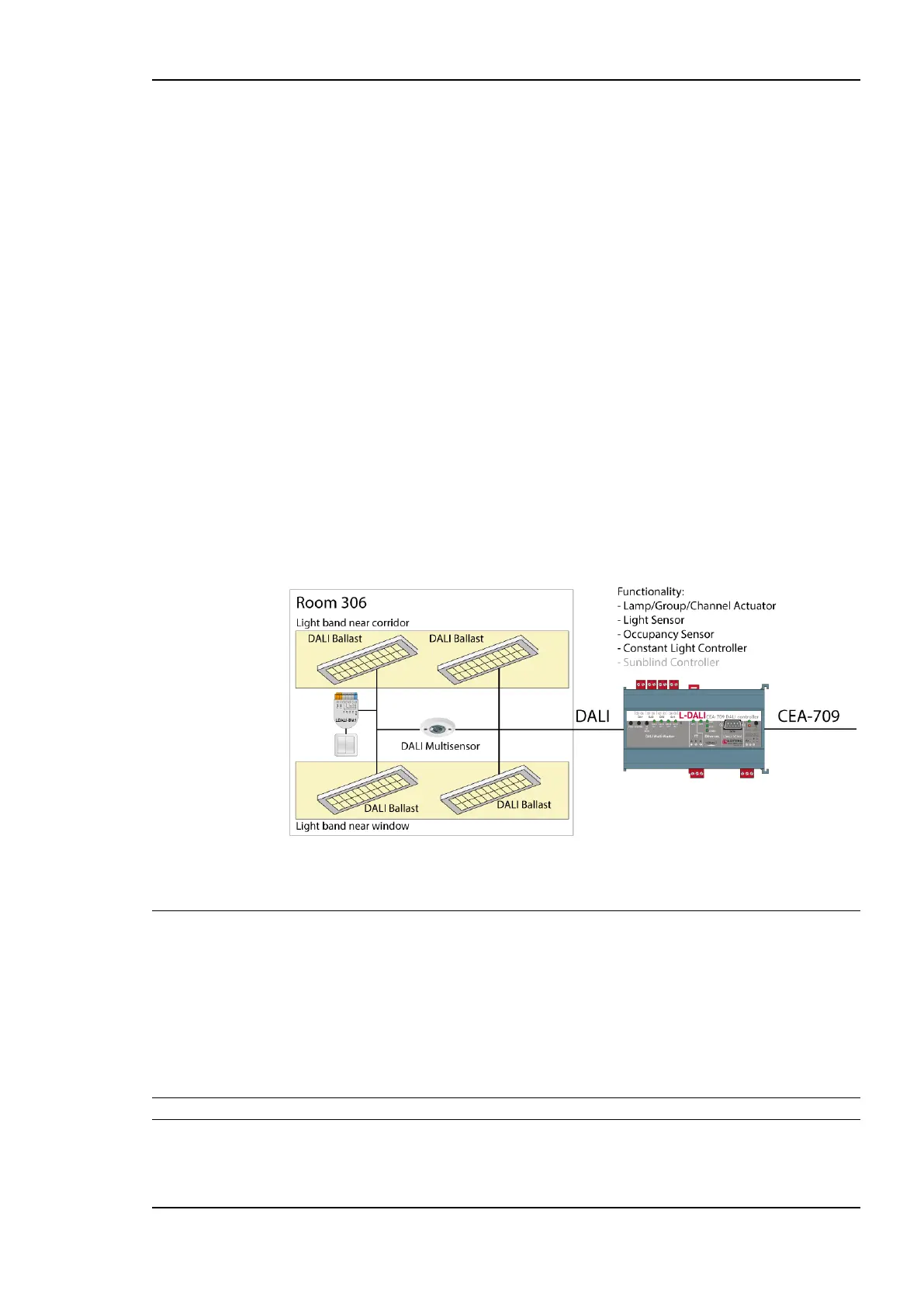
simple project shown in Figure 4.
The project consists of a single room (Room 306) which is illuminated by four DALI lamps.
Two of those lamps form a light band near the windows of the room and the other two
lamps form a light band near the corridor. The room is equipped with a DALI multi-sensor
which acts as both a light sensor and an occupancy sensor. The build-in constant light
controller of the L-DALI device uses the input from the DALI multi-sensor and dims the
DALI ballasts accordingly. For manual override a DALI push-button is installed. The
sunblind controller is not used in this quick-start example.
Figure 4: Quick-Start Example Project.
3.1 Hardware Installation
3.1.1 Models without built-in DALI Bus Power Supply
For models without built-in DALI bus power supply it is recommended to use the
LDALI-PWR4-U or LDALI-PWR2-U power supply together with the L-DALI. Connect the
L-DALI to the LDALI-PWR4-U and to the DALI network as shown in Figure 5. To allow
for easy configuration it is recommended to always connect the L-DALI to the Ethernet
network. More detailed instructions are given in Chapter 4.
Important: Do not connect terminal 26 to earth ground!
After the DALI ballasts have been installed and connected to the DALI network, the
installation can be tested by following these steps: