L-DALI User Manual 76 LOYTEC
Version 5.2 LOYTEC electronics GmbH
For further details on the functionality of the constant light controller applications see
sections 8.2.8 (LDALI-10X models) and 8.3.5 (LDALI-20X models).
5.3.3 DALI Groups
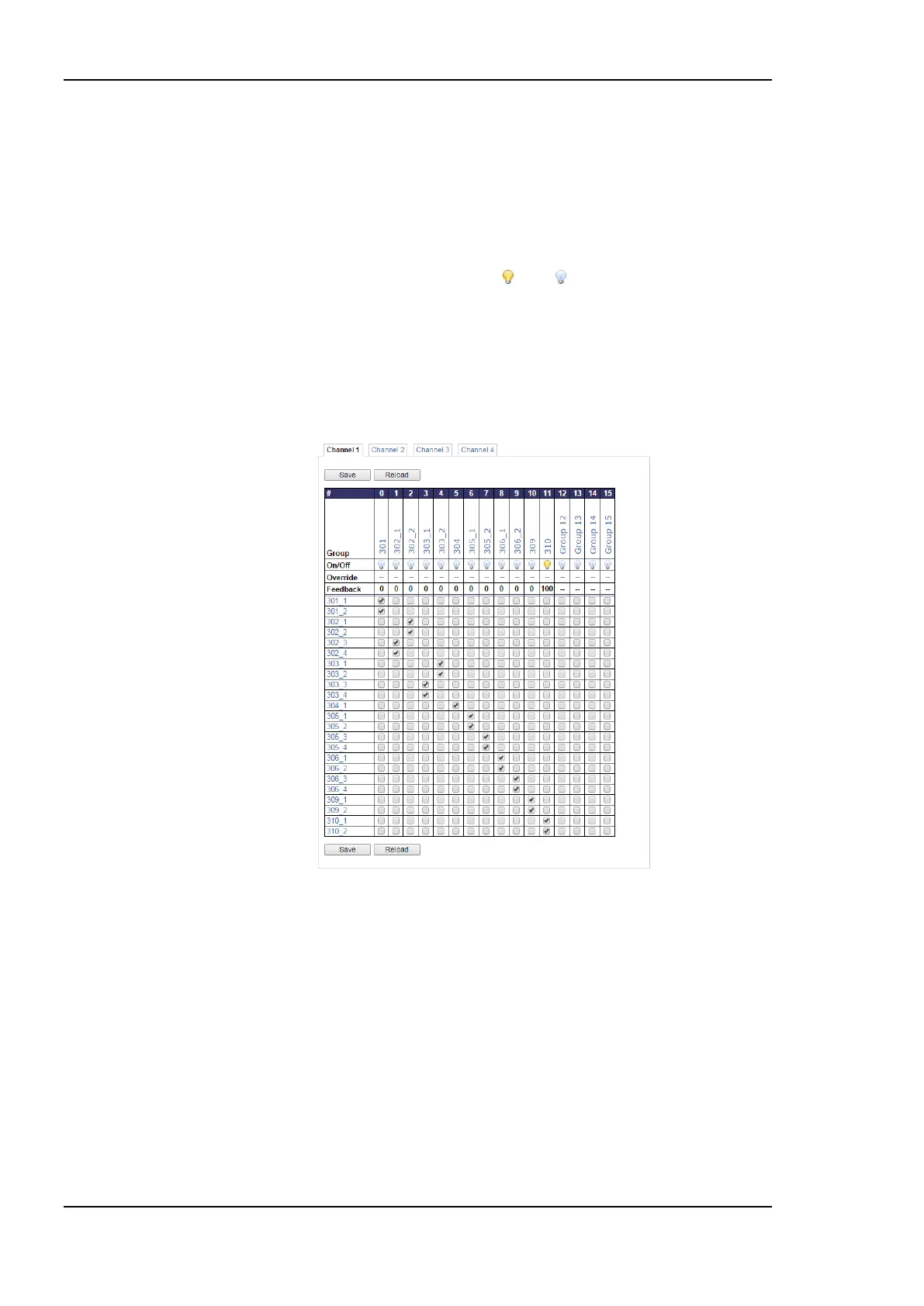
The DALI ballasts can be assigned to DALI groups as shown in Figure 71. Check the check
box to add ballasts to groups, uncheck it to remove a ballast from a group. Commit changes
by clicking on the Save button.
The lamp symbol shows whether the group is on or off . Clicking on it toggles the group
between override to on, override to off and automatic mode. In the Override row a dim
level override can be entered. Enter ‘--‘ to relinquish the override. In the Feedback row
below the current average dim value (0%-100%) of the group is shown.
Click on the name to jump to the data point configuration page of the fieldbus object
corresponding to the group. The name can be changed by editing the nciLocation
(LONMARK) or Object_Name (BACnet) property.
Figure 71: DALI Group Configuration.
5.3.4 DALI Installation
Figure 72 shows the initial DALI configuration page. If the device offers multiple DALI
channels, the channel can be selected by clicking on the different tabs at the top of the page
labeled Channel 1, Channel 2, etc.
If there is a problem with the DALI bus power on the selected channel, “Bus supply failed”
will be displayed in the upper right corner of the tab.
The page is separated in three sections:
1. Devices in Database: Lists all devices on the DALI channel which were already
commissioned.