L-DALI User Manual 43 LOYTEC
Version 5.2 LOYTEC electronics GmbH
CEA-709 L-DALI: /CEA709 DALI Channel 1/Datapoints/Constant Light
Controllers/Constant Light Controller 0/
The page will look like in Figure 34.
2. The parameters of the selected constant light controller are displayed on the right side.
Change the constant light controller mode (parameter nciClMode or Mode) to
REGULATOR. This parameter selects the operating mode. The REGULATOR mode
is used if a light/occupancy sensor is installed which measures the indoor illumination.
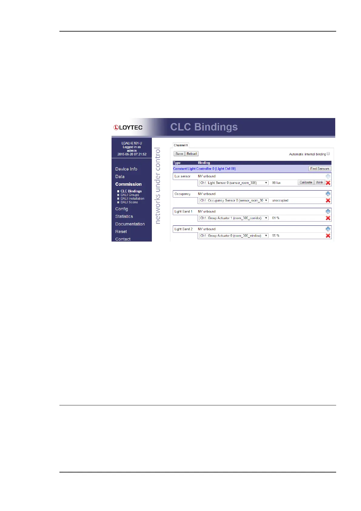
Figure 35: DALI Installation Web Interface: CLC Bindings.
3. Change the setpoint of the constant light controller (parameter nciLuxSetpoint or
Setpoint) to the desired light level (e.g. 400 lux).
4. You can leave the default values for the remaining parameters. For a description of the
constant light controller functionality and the parameters refer to Section 8.2.8
(CEA-709) and 8.3.5 (BACnet).
5. To determine which sensors (occupancy & lux) are used as inputs to and which light
groups are controlled by a constant light controller instance go to the CLC Bindings
page (see Figure 35).
6. Again, selected the DALI channel by clicking on the different tabs at the top of the
page labeled Channel 1, Channel 2, etc.
7. Click on the Add to add an input or output. Use the drop down box to select a sensor
(input) or a light group (output). In our example we use “sensor_306” for lux and
occupancy sensor inputs, group “306_corridor” as output of the first (brighter) light
band and group “306_window” as output for the second (darker) light band.
3.6 Configuration of BACnet Interface (LDALI-20X only)
3.6.1 Configure BACnet Interface
To allow integrating the L-DALI to a BACnet network a network wide unique device ID
and device name must be configured. This is best done using the web interface: