LPKF Laser & Electronics AG | V. 1.0
Creating rubout areas
Rubout areas enable to produce an especially precise isolation in defined areas. The
residual copper is partially or completely removed depending on the isolation method.
A rubout area is created on the Top layer of the current layout around the pads of the
IC.
1. Click on Insert > Rubout area > RuboutTop.
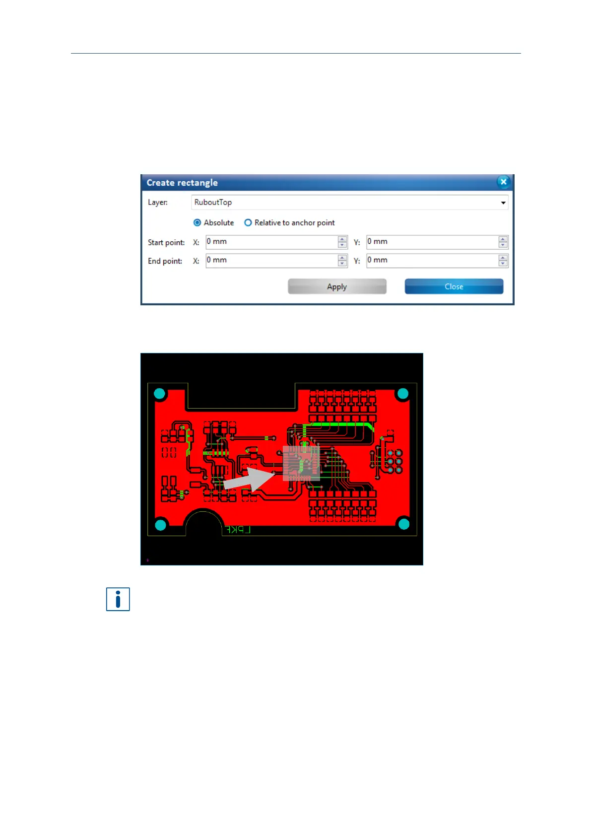
The following dialog is displayed:
Fig. 70: Create rectangle to create a rubout area
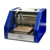
2. Draw a rectangle around the IC's pads of the layout or enter the coordinates of the
corners in Start point and End point:
Fig. 71: Rectangle surrounding the IC pads
It can be helpful to hide other layers to draw the rubout area depending on which layer
the rubout area is to be created.
The presentation of the objects on the individual layers can be defined in the pane
Layers.
3. Click on [Close].
The rubout area has been created.