214325 153 Revision A
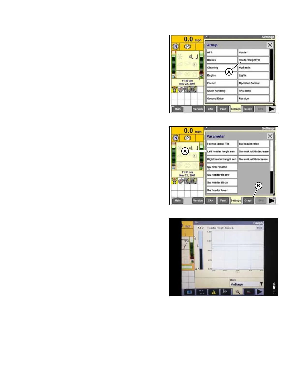
Figure 5.31: Case IH Combine Display
8. Select HEADER HEIGHT/TILT (A). The PARAMETER
page opens.
Figure 5.32: Case IH Combine Display
9. Select LEFT HEADER HEIGHT SEN (A), and then
select GRAPH button (B). The exact voltage is
displayed at top of page. Raise and lower header to see
full range of voltage readings.
Figure 5.33: Case IH Combine Display
10. Adjust voltage limits (refer to Adjusting Voltage Limits,
page 142) if sensor voltage is not within low and high
limits or if range between low and high limits is
insufficient (refer to Table 5.1, page 140).
SETTING UP AUTO HEADER HEIGHT CONTROL