214325 68 Revision A
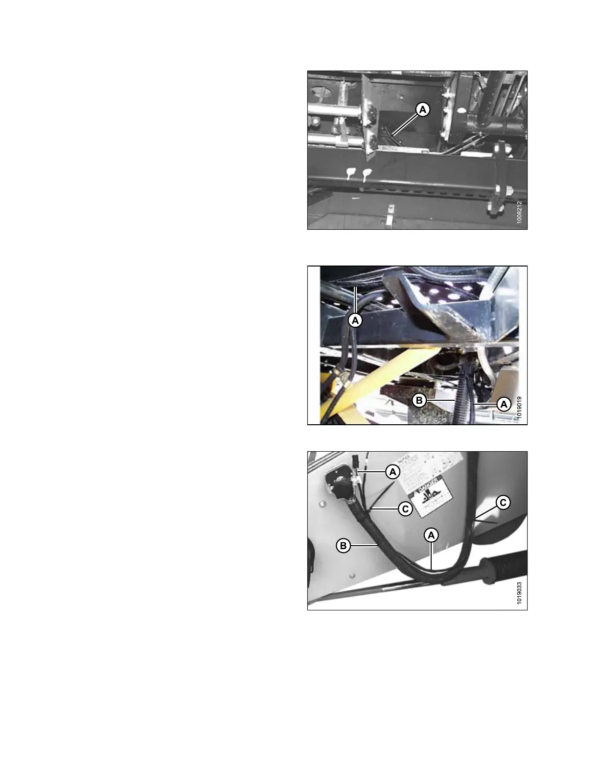
Figure 3.122: Cab Underside of
CLAAS 500 Series
26. Route switch harness (A) under the cab floor alongside
the existing harnesses. Do NOT secure harness with
cable ties until routing is complete.
Figure 3.123: CLAAS 500 Series Shown
27. Route switch harness (A) between cab floor and frame,
from bottom left corner of cab to conduit (B), and along
conduit (B) to multicoupler.
Figure 3.124: Combine Multicoupler
28. Secure wiring harness (A) to conduit (B) (starting from
the multicoupler end) with cable ties (C) at
locations shown.
ASSEMBLING HEADER AND ADAPTER