214683 99 Revision A
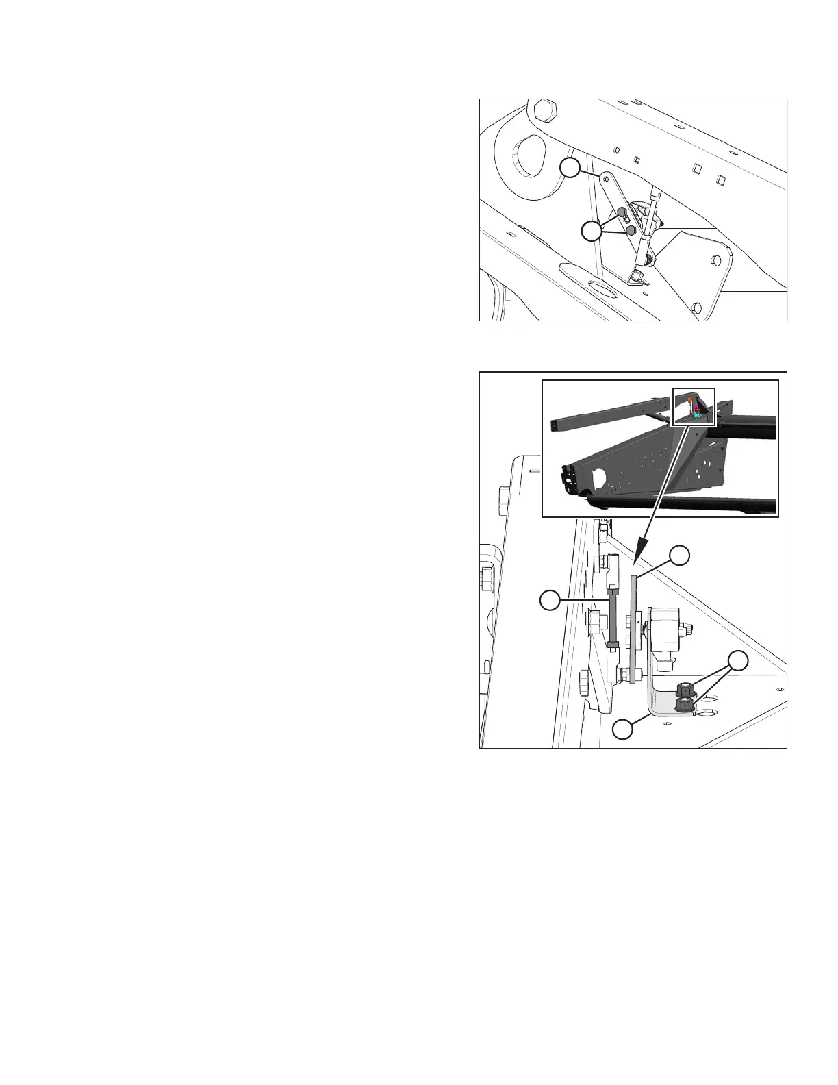
Figure 3.104: Reel Height Sensor – Right
Reel Arm
7. Connect sensor arm (B) using retain hex head bolts (A).
Torque head bolts (A) to 4 Nm (35 lbf·in.).
8. Connect the sensor to the harness.
Figure 3.105: Reel Height Sensor – Right Reel
Arm (Front View)
9. Check that sensor arm and the threaded rod are
parallel. If not, loosen two center lock flange nuts (A),
and adjust sensor mounting bracket (B) until the
threaded rod (C) is parallel with the sensor arm (D).
Tighten center lock flange nuts.
10. Check the sensor voltage range. Refer to Checking and
Adjusting Reel Height Sensor, page 96.
3.7.11 Reel Fore-Aft Position
Reel fore-aft position is a critical factor for achieving the best results in adverse conditions. The factory-set reel
position suits normal conditions, but the fore-aft position can be adjusted as required using the controls inside the
cab.
The reel on non-European-configured headers can be moved approximately 227 mm (9 in.) farther aft by
repositioning the fore-aft cylinders on the header’s reel arms to accommodate certain crop conditions. Refer to
Repositioning Fore-Aft Cylinders on Non-European-Configured Headers, page 101.
OPERATION