214683 131 Revision A
Adjusting Voltage Limits: One-Sensor System
Follow this procedure if you have checked the voltage range (either manually or from the cab) and found that the
sensor voltage is not within the low and high limits or that the range between the low and high limits is insufficient.
DANGER
To avoid bodily injury or death from unexpected start-up of machine, always stop engine and remove key
from ignition before leaving operator’s seat for any reason.
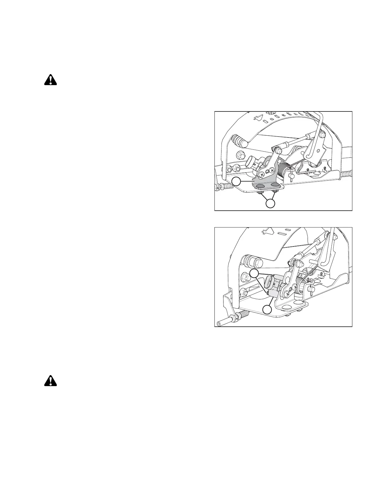
Figure 3.165: AHHC Sensor Assembly
1. Follow these steps to adjust the high voltage limit:
a. Extend guard angle fully; the header angle
indicator should be at D.
b. Position header 152–254 mm (6– 10 in.) above the
ground; the float indicator should be at 0.
c. Check the high voltage limit using the combine
display or a voltmeter. Refer to Table 3.20, page
126.
d. Loosen sensor-mounting nuts (A).
e. Slide sensor support (B) to right to increase high
voltage limit or to left to decrease it.
f. Tighten sensor-mounting nuts (A).
Figure 3.166: AHHC Sensor Assembly
2. Follow these steps to adjust the low voltage limit:
a. Extend guard angle fully; the header angle
indicator should be at D.
b. Fully lower header on the ground; the float indicator
should be at 4.
c. Check the low voltage limit using the combine
display or voltmeter. Refer to Table 3.20, page 126.
d. Loosen sensor-mounting nuts (A).
e. Rotate sensor (B) clockwise to increase low
voltage limit and counterclockwise to decrease it.
f. Tighten sensor-mounting nuts (A).
3. After making adjustments, recheck both the upper and lower voltage limits to make sure they are within the
required range according to Table 3.20, page 126.
Adjusting Voltage Limits: Two-Sensor System
DANGER
To avoid bodily injury or death from unexpected start-up of machine, always stop engine and remove key
from ignition before leaving operator’s seat for any reason.
1. Extend guard angle fully; the header angle indicator should be at D .
2. Position header 150–254 mm (6–10 in.) above the ground; the float indicator should be at 0.
OPERATION