214683 428 Revision A
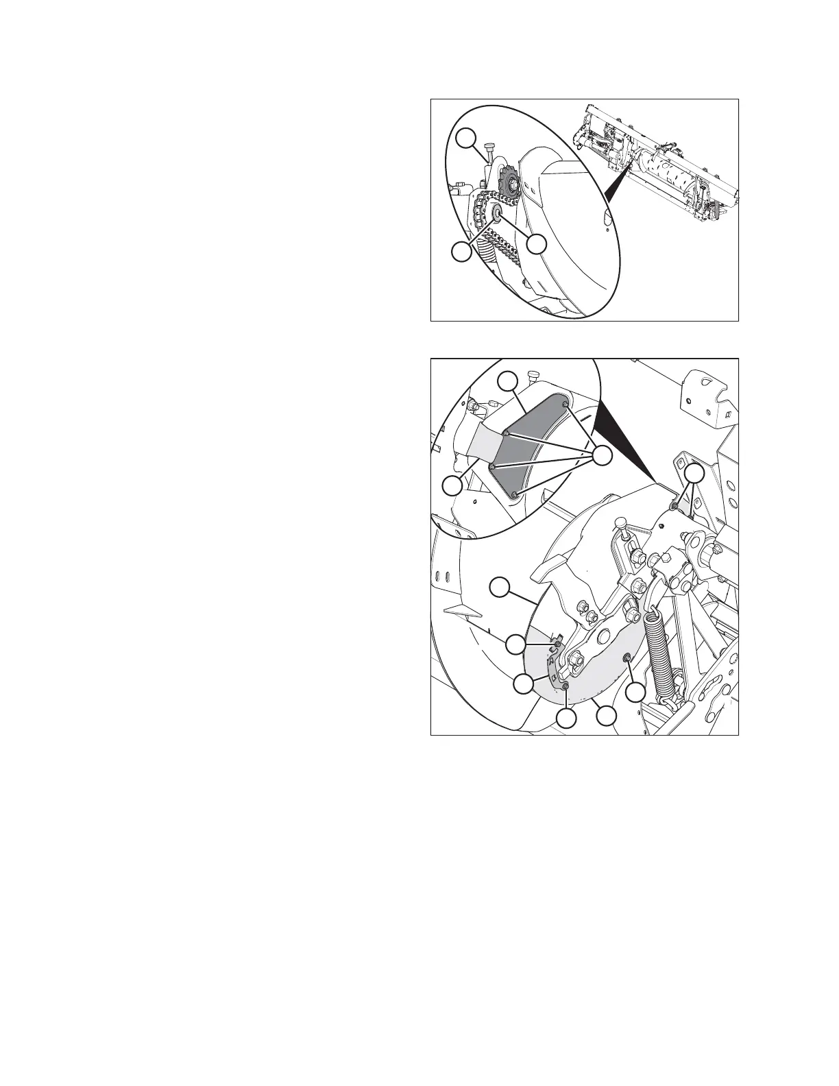
Figure 5.65: Auger Drive (Left Side)
8. Tighten the jam nut (A).
9. Apply medium-strength threadlocker (Loctite
®
243 or
equivalent) to threads of screw (B).
10. Install washer (C) and secure it with screw (B).
Figure 5.66: Left Side of Auger
11. Position bottom cover (H) and secure with bolt and
washer (J).
12. Position top cover (G). Secure top and bottom cover
with clamp/indicator (D) and bolts (C).
13. Install inspection panel (B) and secure with four
bolts (A). Tighten bolts (A) and torque to 2.7–4.1 Nm
(24–36 lbf∙in).
14. Install cover retainer (F) and secure with two bolts (E).
5.7.6 Using Auger Flighting
The auger flighting on the FM100 can be configured for specific combines and crop conditions. Refer to 4.1 Float
Module Feed Auger Configurations, page 307 for combine/crop specific configurations.
5.7.7 Auger Fingers
The FM100 auger uses retracting tines to feed the crop into the combine feeder house. Some conditions may
require the removal or installation of fingers for optimal crop feeding. Replace any worn or damaged fingers.
IMPORTANT:
Only install hollow fingers in a FM100. The use of solid fingers will cause severe damage to the machine.
MAINTENANCE AND SERVICING