214683 327 Revision A
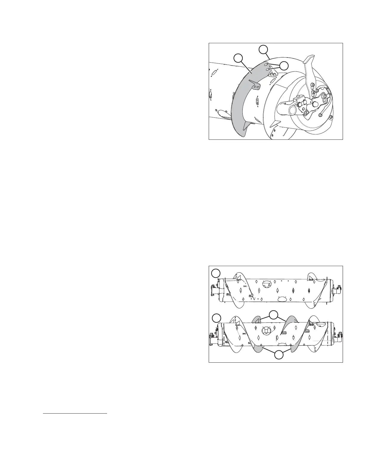
Figure 4.41: Right Side of Auger
26. Place bolt-on flighting (A) outboard of the other
flighting (B) on the right side of the auger as shown.
27. Temporarily secure bolt-on flighting (A) with two button
head bolts and nuts at location (C).
28. Repeat Steps 20, page 326 to for both pieces of
flighting on the right side of the auger.
29. Install flighting slot plugs (MD #213084) in the flighting
mounting locations and secure with M6 bolts and
tee nuts.
30. Torque all nuts and bolts to 47 Nm (35 lbf·ft) to eliminate
deflection on flighting, then retorque them to 58–64 Nm
(43–47 lbf·ft).
NOTE:
The flighting should fit tightly against the auger tube; however, gaps are not uncommon. Crop material may collect
in these gaps, but this should not affect performance. If desired, use silicone sealant to fill these gaps.
31. Add or remove auger fingers to optimize feeding for your combine and crop conditions. Refer to Installing Feed
Auger Fingers, page 431 or Removing Feed Auger Fingers, page 429.
32. If not adding or removing auger fingers, reinstall all access covers and secure with bolts. Coat bolts with
medium-strength threadlocker (Loctite
®
243 or equivalent) and torque to 8.5 Nm (75 lbf∙ in).
4.1.9 Converting from Narrow Configuration to Ultra Narrow Configuration
Two kits of either MD #287032 or B6400
50
and some hole-drilling are required to convert to this configuration. Extra
hardware is included in these kits. Be sure to use the correct hardware at the correct location to prevent damage
and to maximize performance.
Figure 4.42: Auger Configurations (Rear View)
1 - Narrow Configuration 2 - Ultra Narrow Configuration
NOTE:
Additional holes on the auger are needed before these
flightings (A) can be installed.
HEADER ATTACHMENT/DETACHMENT
50. MD #287032 is available only through MacDon Parts. B6400 is available only through Whole Goods. Both kits
contain wear-resistant flightings.