214683 36 Revision A
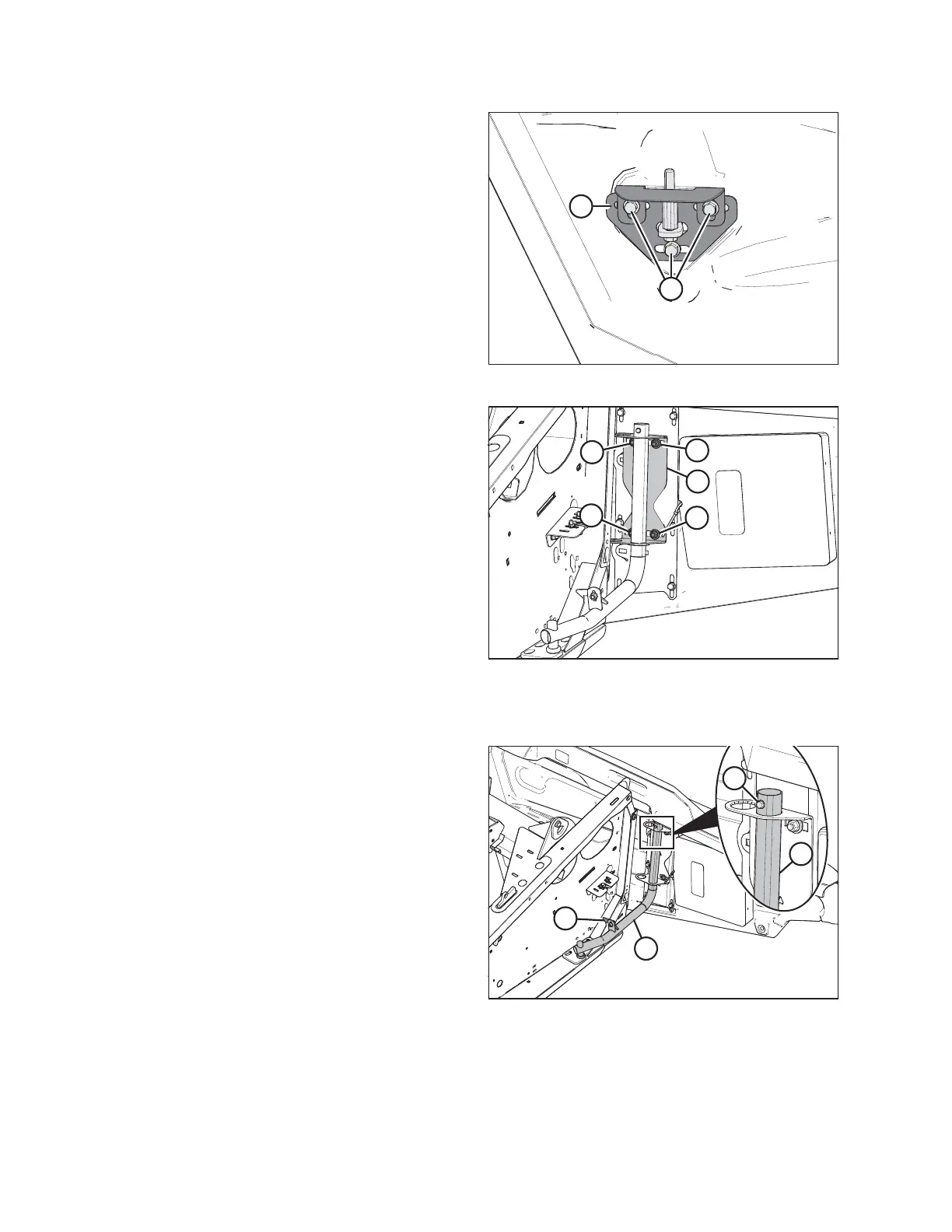
Figure 3.14: Left Endshield Latch Assembly
2. Loosen the three bolts (A) on latch assembly (B).
3. Adjust latch assembly (B) to achieve the desired gap
between the front end of the shield and the header
frame. Refer to Table 3.1, page 35 for the
recommended endshield gap at various temperatures.
4. Tighten the three bolts (A) on the latch assembly.
Figure 3.15: Left Endshield Support Tube
5. Tighten the four bolts (A) on support tube bracket (B).
6. Close endshield.
Removing Endshields
Figure 3.16: Left Endshield
1. Fully open the endshield. For instructions, refer to
Opening Endshields, page 33.
2. Engage lock (A) to prevent endshield movement.
3. Remove self-tapping screw (B).
4. Slide endshield upwards and remove from hinge
arm (C).
5. Place endshield away from work area.
OPERATION