214683 132 Revision A
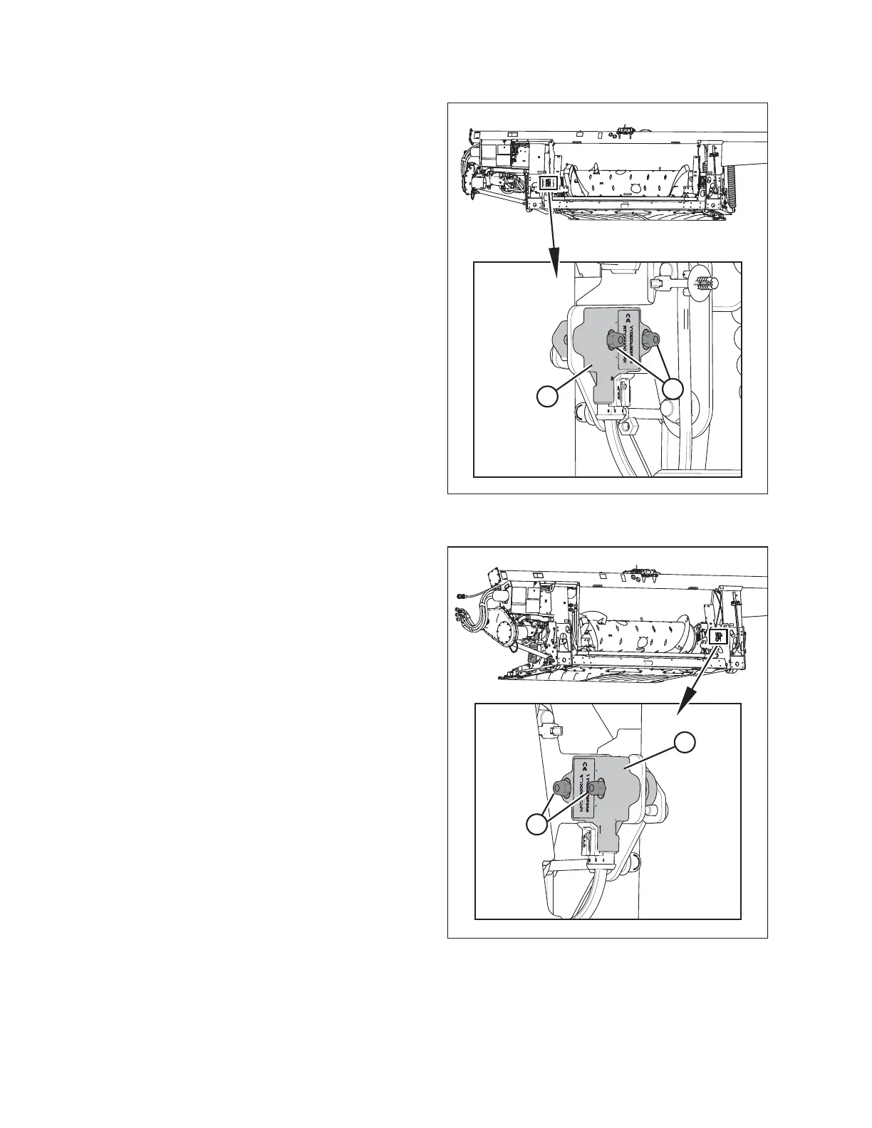
Figure 3.167: Optional Two-Sensor Kit –
Left Sensor
3. Follow these steps to adjust left sensor voltage:
a. Loosen sensor-mounting nuts (A).
b. Rotate sensor (B) counterclockwise to lower the
voltage. Rotate sensor clockwise to raise the
voltage.
c. Check that the left sensor is at the correct high
voltage limit.
d. Tighten sensor-mounting nuts (A).
Figure 3.168: Optional Two-Sensor Kit –
Right Sensor
4. Follow these steps to adjust right sensor voltage:
a. Loosen sensor mounting nuts (A).
b. Rotate sensor (B) clockwise to lower the voltage.
Rotate sensor counterclockwise to raise the
voltage.
c. Check that the right sensor is at the correct high
voltage limit.
d. Tighten sensor mounting nuts (A).
OPERATION