Manitowoc Published 05-09-17, Control # 011-29 3-21
16000 OPERATOR MANUAL OPERATING CONTROLS AND PROCEDURES
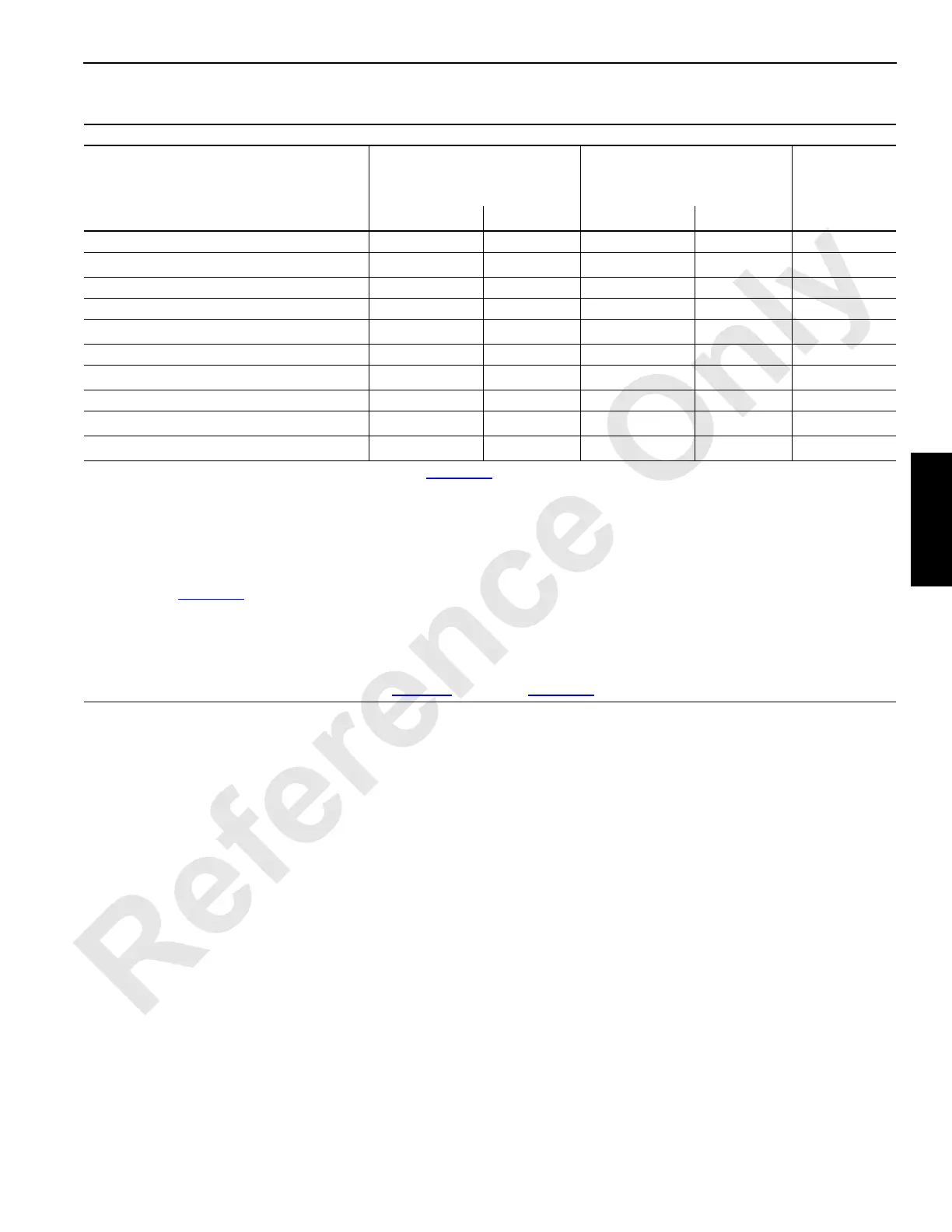
Table 3-3 Bypassable Limit Identification
NOTE: Cranes meeting 2010 European requirements are equipped an RCI/RCL External Override Switch located outside
the operator’s cab (see Rated Capacity Indicator/Limiter Operation Manual.)
This Table Applies Only to Cranes without Limit Bypass Switch (D4)
Limit
8
Limit Bypass Switch (D3)
(momentary key switch)
Limit Bypass Switch (D3)
(momentary key switch)
Luffing Jib Setup Mode On
1
External
Override
Switch
2
Non-CE
3
CE
3
Non-CE
3
CE
3
CE
3
Boom Up [55] No No No No No
Block Up (each drum) [60] Yes
Yes
6
Yes Yes No
Minimum Bail (each drum) [57] Yes No No No No
Luffing Jib Maximum Up 1 [49] Yes No Yes Yes No
Luffing Jib Maximum Up 2 [73]
Yes
4
No
Yes
4
Yes
4
No
Luffing Jib Maximum Down 1 [50] Yes No Yes Yes No
Luffing Jib Maximum Down 2 [67]
Yes
5
No
Yes
5
No No
Mast Too Far Forward [66] Yes Yes No No No
Rated Capacity Indicator/Limiter [54] Yes
Yes
6
Yes
Yes
6
Yes
7
MAX-ER
®
Mast Stop Limit Switch
[27] No No No No No
1
Use only for rigging. See procedure described on page 3-23 for Turning on Luffing Jib Setup Mode.
2
See Rated Capacity Indicator/Limiter Operation Manual.
3
CE = Cranes that comply with 2010 European requirements (see NOTE below).
4
Only when boom is below 50°
5
When this limit is contacted, operation will stop and you will not be able to continue lowering luffing jib. See Luffing Jib Max
Down 2 on page 3-29
for detailed instructions.
6
Only if boom or luffing jib is below allowable angle given in Capacity Chart (while raising or lowering boom and luffing jib
from or to ground level).
7
The speed of the crane functions is limited to 15% of their maximum speed for movements that increase load.
8
Numbers in brackets [ ] are fault codes. See Table 3-4 starting on page 3-52.
 Loading...


