Setting up the F6 SMART™ System
F6 SMART™ – Volumetric Handheld Camera – User Guide
♦ A New bar with its associated Add path Command-Button, at the top.
♦ A center window listing all F6 SMART™ Cameras assigned to the
workstation.
♦ Three (3) Command-Buttons – Delete, Choose and Close.
For the initial uploading of the calibration files focus is made on the following steps
only. Other parts of this Dialog-Box are detailed in paragraph Settings Menu –
Camera Command-Button on page 51 below.
6. Type into the New bar a sub-directory name for storage of the calibration files of the
new F6 SMART™ Camera.
The new sub-directory’s name to be used should be the F6 SMART™ Camera’s
unique Serial Number (S/N).
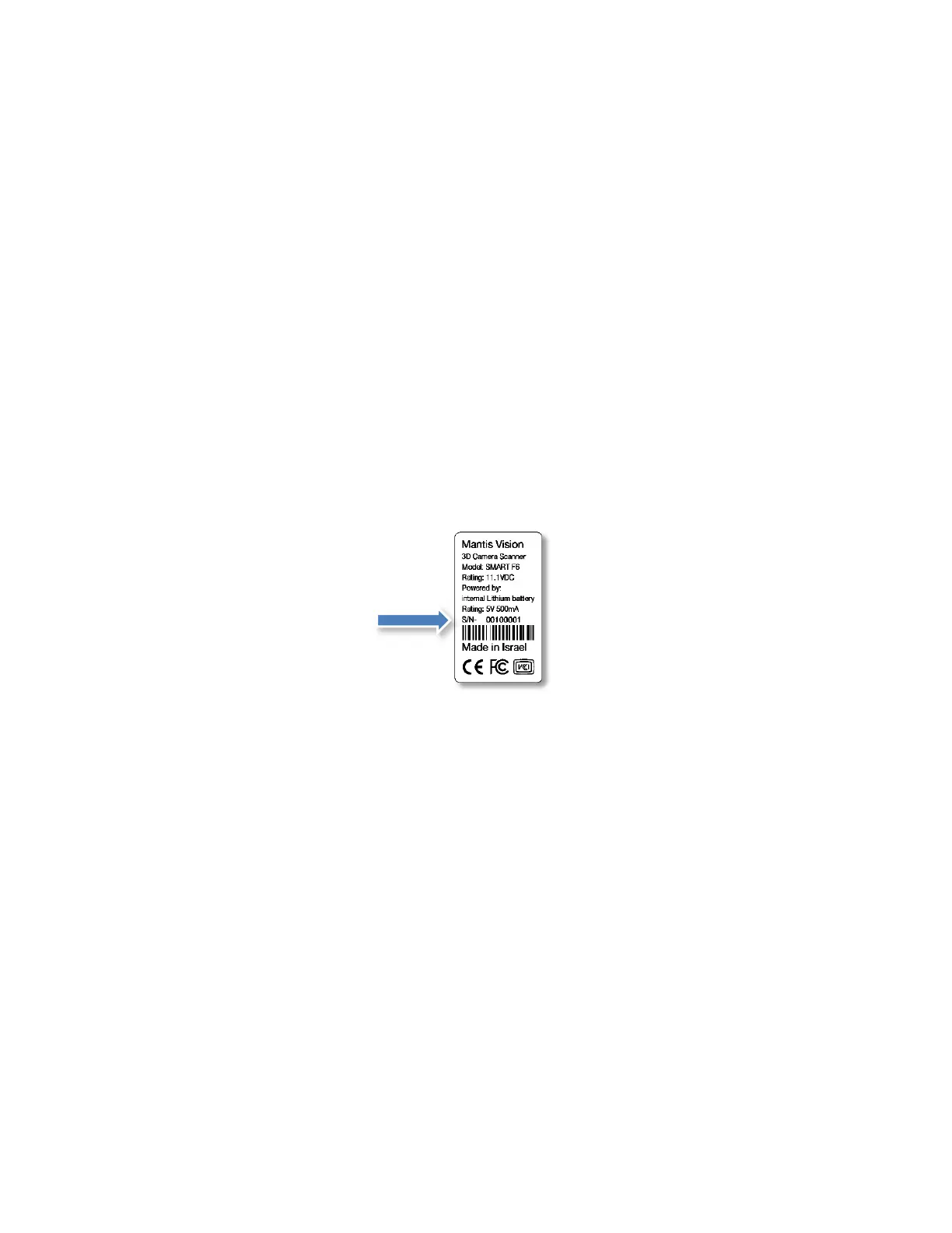
This serial number can be found on the barcode label attached to the bottom end of
the F6 SMART™ Camera’s body:
Figure 30 – F6 SMART™ ID Barcode Label
7. Click on the Add path Command-Button.
The newly created sub-directory is added to the center window listing all F6 SMART™
Cameras assigned to the workstation.
8. Copy-paste the three (3) calibration files from the Flash Drive into this sub-directory.
9. Click on the newly added F6 SMART™ Camera name and then click on the Choose
Command-Button to set it as the system’s active F6 SMART™ Camera.
The Cameras Dialog-Box will close and the system has its F6 SMART™ Camera’s
calibration files uploaded and set for operation.
The initial setup of the system is completed.
Other setups will also be required for well-tuned scanning. These will be detailed
throughout the process of scanning below.