OPERATION4 - 5
D-MAXE with OI-B/OI-N www.maxcessintl.comMI 2-296 1 D
Operating area
7 The graphic (bitmap) shows the processor and drive
selected for the current situation (not in "Servo-Center"
operating mode)
8 The currently selected operating mode
9 In "Automatic“ and "Manual" modes, the bar graph shows
the signal level of the active sensor
In "Servo-Center mode, the bar graph shows the signal level
of the Servo-Center transducer
10 A graphic next to the F1 to F6 keys identifies the active
functionality of the corresponding keys
11 A narrow rectangle between the key and graphic identifies
the status of a key:
Filled rectangle:
The function is active
Hatched rectangle:
Key is available for use
Empty rectangle:
Key disabled because a
Remote
Control
is currently running
this function
No rectangle:
Key is not enabled
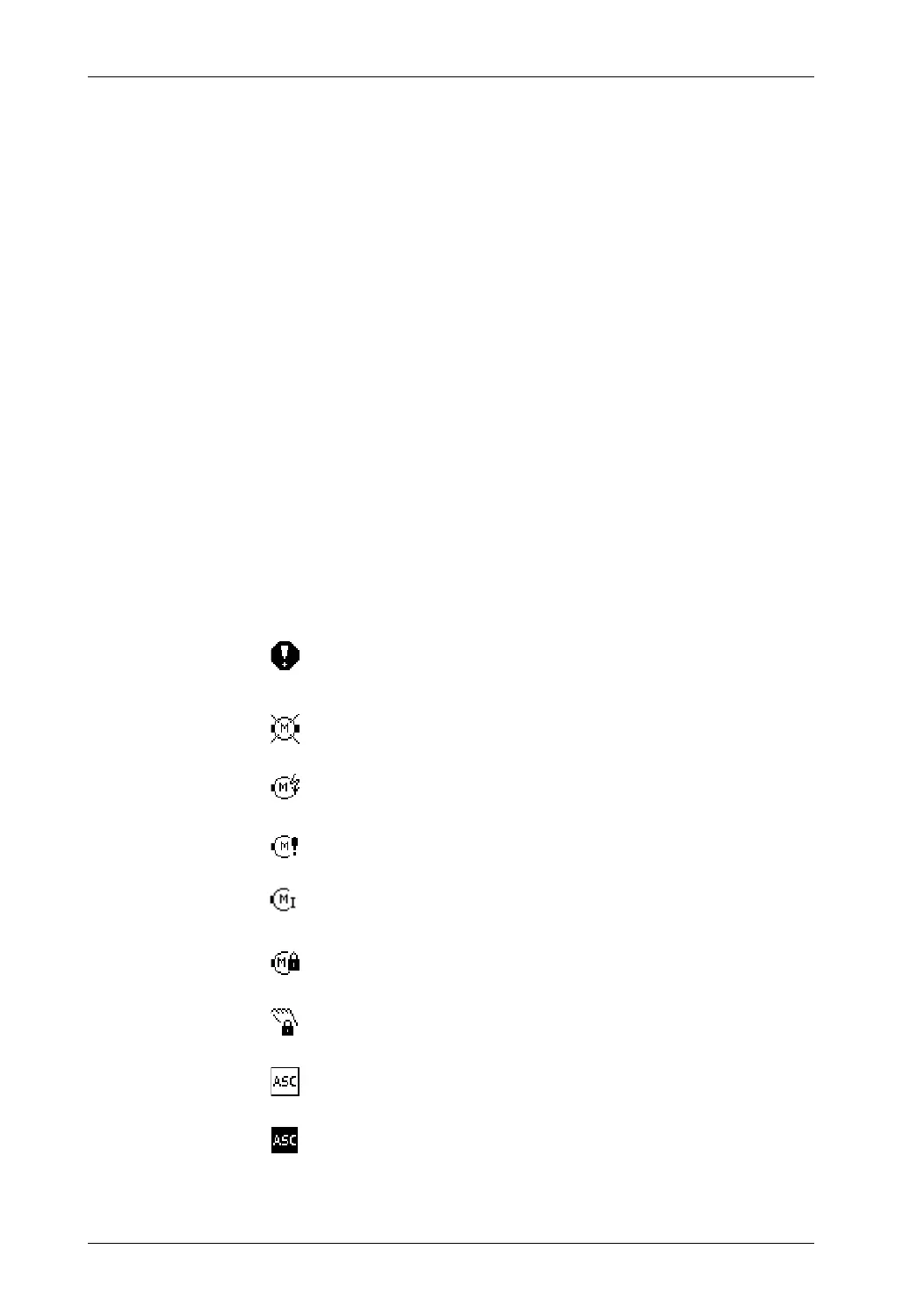
12 Display of status symbols
The following icons can be displayed at this position. The
status displays appear at position 3.
[0001] Error display.
This icon appears if an error is detected on the selected
"device".
[0002] No motor was detected or no motor is connected.
[0004] The motor current supply is outside the valid range.
[0006] Power feedback from motor (motor acting as generator)
[n/a] Motor at maximum current
[0100] The motor is locked.
[8000] The motor is actively locked in "Manual" mode (hardlock).
[0010] ASC is activated
[0020] ASC is triggered.
This icon appears if the ASC function has been activated
and triggered on the selected drive.