5.4 Parameter description
79
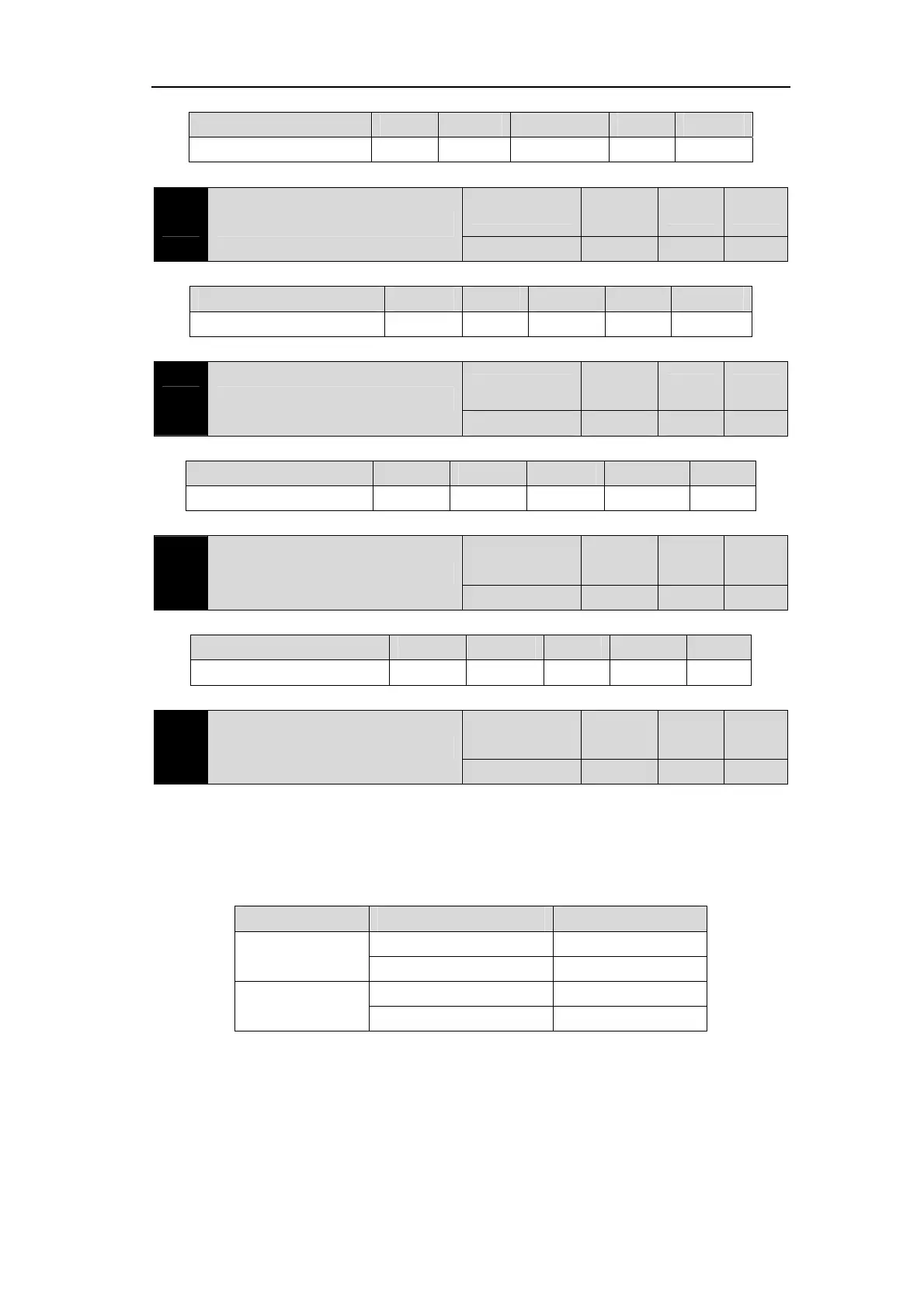
Corresponding functions are represented by 5-bit binary:
Digital bit4 bit3 bit2 bit1 bit0
Corresponding function CINV CZERO ZCLAMP TCW TCCW
Description of other reference parameter P120.
P122 Digital input DI force valid 3
Range
Default
value
Unit Usage
00000~11111 00000 ALL
Corresponding functions are represented by 5-bit binary:
Digital bit4 bit3 bit2 bit1 bit0
Corresponding function TRQ2 TRQ1 SP3 SP2 SP1
Description of other reference parameter P120.
P123 Digital input DI force valid 4
Range
Default
value
Unit Usage
00000~11111 00000 ALL
Corresponding functions are represented by 5-bit binary:
Digital bit4 bit3 bit2 bit1 bit0
Corresponding function GEAR2 GEAR1 GAIN CMODE EMG
Description of other reference parameter P120.
P124 Digital input DI force valid 5
Range
Default
value
Unit Usage
00000~11111 00000 ALL
Corresponding functions are represented by 5-bit binary:
Digital bit4 bit3 bit2 bit1 bit0
Corresponding function REF GOH PC INH CLR
Description of other reference parameter P120.
P130 Digital output DO1 function
Range
Default
value
Unit Usage
-28~28 8 ALL
Digital output DO1 function planning, absolute value of parameter represents function,
symbol represents logic, please refer to Section 5.3 for function.
0 forces OFF and 1 forces ON.
Signs represent output logic, positive numbers represent positive logic, and negative
numbers represent negative logic:
Parameter value Corresponding function DO output signal
Positive number
ON Conduction
OFF Cut-off
Negative number
ON Cut-off
OFF Conduction