5-1
COMPONENT TESTING
Electrical Shock Hazard
Disconnect power before servicing.
Replace all parts and panels before operating.
Failure to do so can result in death or electrical shock.
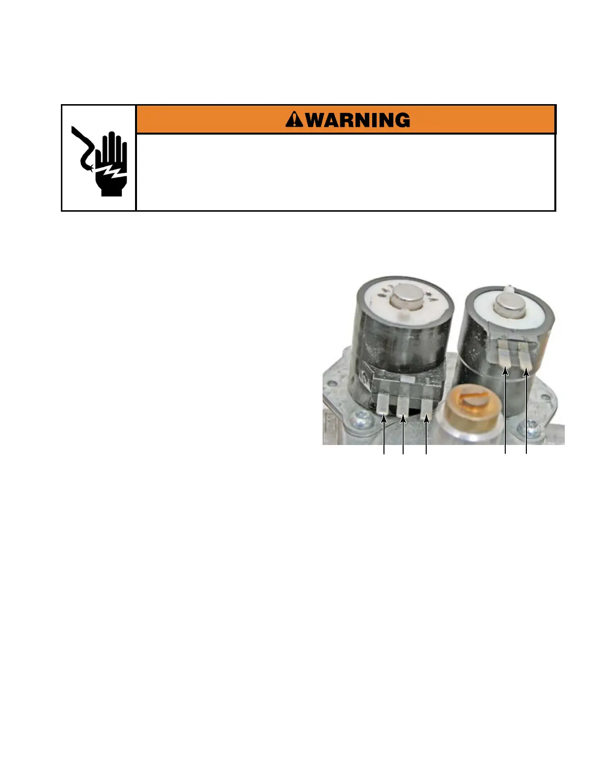
GAS VALVE COILS
The gas valve is actually a regulator and 2
valves in 1. One valve is in series with the
other.
The rst valve has a split coil and requires
both coils to lift the armature, but only 1 coil
to hold it open. The second or secondary coil
requires only 1 coil.
Unplug dryer or disconnect power.
Turn off gas supply to dryer.
Access the gas valve coils.
(See page 4-41)
Disconnect the wire connectors from the coil
terminals.
Set ohmmeter to the R X 100 scale.
Set digital ohmmeters to lowest scale.
1.
2.
3.
4.
5.
Touch the ohmmeter test leads to the
indicated coil terminals. The meter should
indicate as follows:
Pins 1 & 2 = 1750 Ω
Pins 1 & 3 = 730 Ω
Pins 4 & 5 = 1750 Ω
All readings ± 5%
NOTE: Black and oily soot on the interior
drum and bulkhead surfaces probably
indicate that the regulator is not set-up for
the proper gas type.
6.
1 2 3 4 5