4-52
Remove the facia (See page 4-50).
Remove the user interface buttons
(See page 4-51).
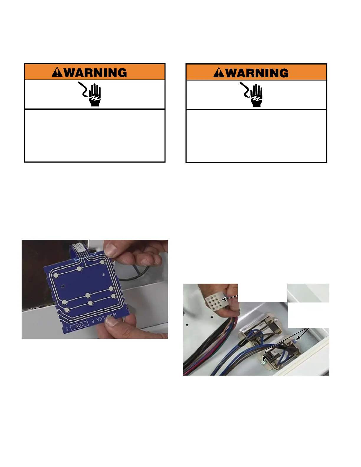
Slide the ribbon connector out of the slot
and remove the membrane.
TECH TIP:
Make sure the end of the ribbon
is folded correctly when reinserting it. The
extra length of plastic at the end of the
ribbon connector must be bent back over
the top of the end of the ribbon connector,
not down and under or it will block the
connections preventing operation.
1.
2.
3.
REMOVE USER INTERFACE
MEMBRANE SWITCH
Electrical Shock Hazard
Disconnect power before servicing.
Replace all parts and panels before
operating.
Failure to do so can result in death or
electrical shock.
Electrical Shock Hazard
Disconnect power before servicing.
Replace all parts and panels before
operating.
Failure to do so can result in death or
electrical shock.
Lower the control board bracket
(See page 4-50).
Remove one 1/4” hex head screw and
loosen the second one that attach the relay
to the collar.
Slide the relay out from under the second
screw.
Remove the wire connectors and the relay.
Repeat this procedure for the other relay.
TECH TIP: The door switch relays are
identical. The wire leads colors are the
same to each relay. To identify which door
switch relay is for which dryer, trace the
wires to identify which leads go to the 12 pin
plug that goes to the upper dryer.
1.
2.
3.
4.
5.
REMOVE DOOR
SWITCH RELAYS
Upper Dryer
12 Pin Plug
Two 1/4”
Hex Head
Screws