6-4
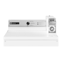
GAS DRYER
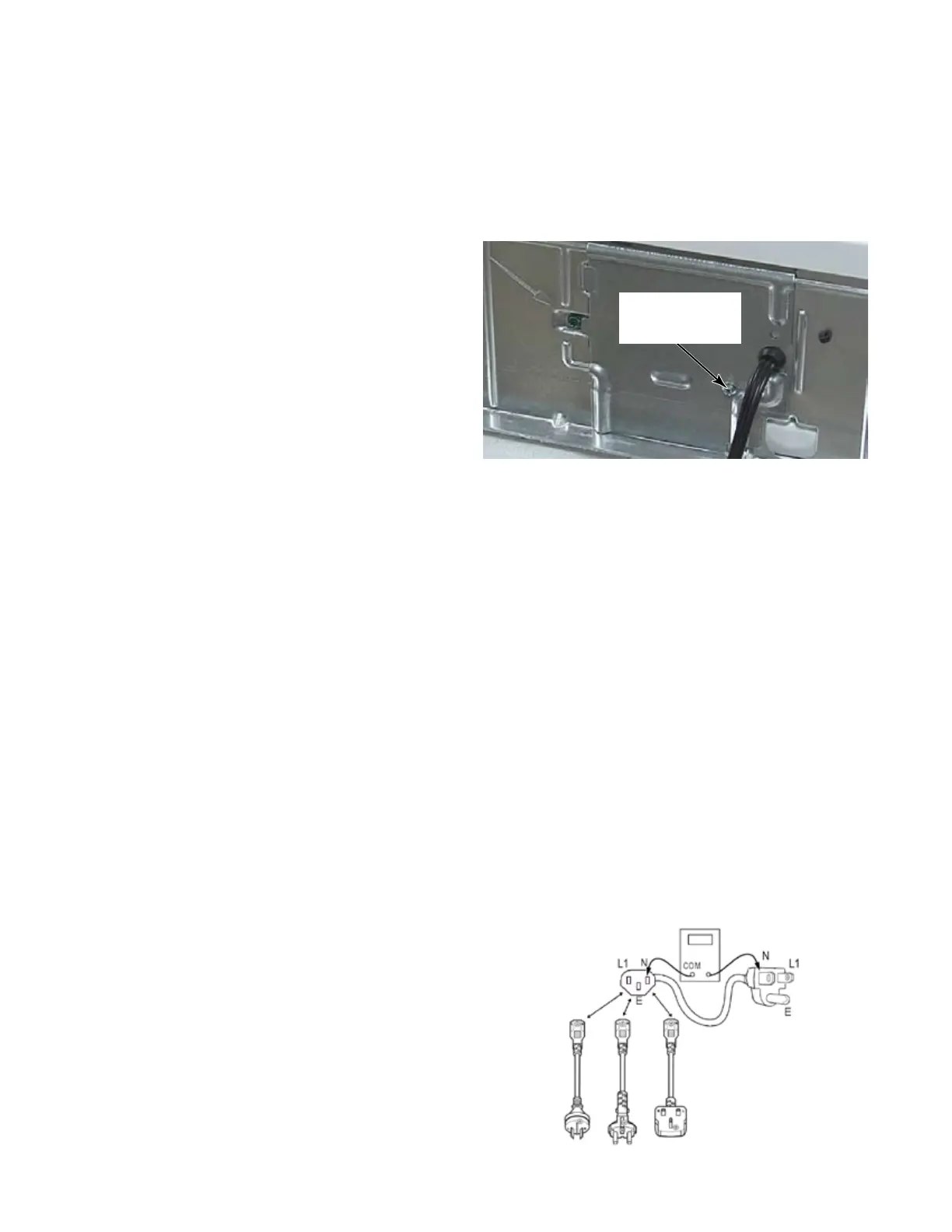
Unplug dryer or disconnect power.
Remove the cover plate from the upper right
corner of the back of the dryer.
Check that the power cord is firmly
connected to the dryer’s wire harness.
Check for continuity (0 Ω) from each plug
end to the wire harness connector just
inside the cover plate. Check continuity of
power cord. (See page 6-3).
Access dryer control electronics without
disconnecting any wiring to the dryer control
board.
With an ohmmeter, check for continuity
(0 Ω) between the neutral (N) terminal of
the plug and white wire (N) of the harness
connector. The left-hand side of the
illustration below shows the position of the
neutral terminal (N) on the power cord plug.
• If there is continuity (0 Ω), go to step 6.
• If there is no continuity, or an open circuit
(infinite Ω) is found, replace the power cord.
Otherwise, go to step 6.
1.
2.
3.
4.
5.
Check for continuity (0 Ω) between the
neutral (N) terminal of the plug and white
wire on the dryer timer fuse or 2-wire
connector on CS, white on the timer motor
for the MN models, the black wire on step
down transformer of the stack electric dryer,
and blue on L1LD of Auto Transformer for
gas stack dryers.
• If there is continuity (0 Ω), go to step 8.
• If there is no continuity and the mechanical
connections of the wire are secure, replace
the main wire harness.
On stack dryers, visually check that the
transformer is connected to the control
board at AA6 and no wires are loose in the
connector.
If steps 6, 7 & 8 pass, then reinstall the
console electronics, console assembly, and
all parts and panels before operating.
Plug in dryer or reconnect power.
Perform the Diagnostic Test to verify repair.
If display segment on stack dryer still does
not light, the dryer control board has failed:
• Unplug dryer or disconnect power.
• Replace the dryer control board.
• Reinstall all parts and panels before
operating.
• Plug in dryer or reconnect power.
• Perform diagnostic test to verify repair.
7.
8.
9.
10.
11.
12.
1/4” Hex
Head Screw
 Loading...