6-6
Check the belt switch, and drive motor.
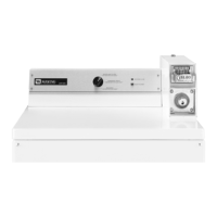
Remove the drum belt from the spring
loaded idler pulley.
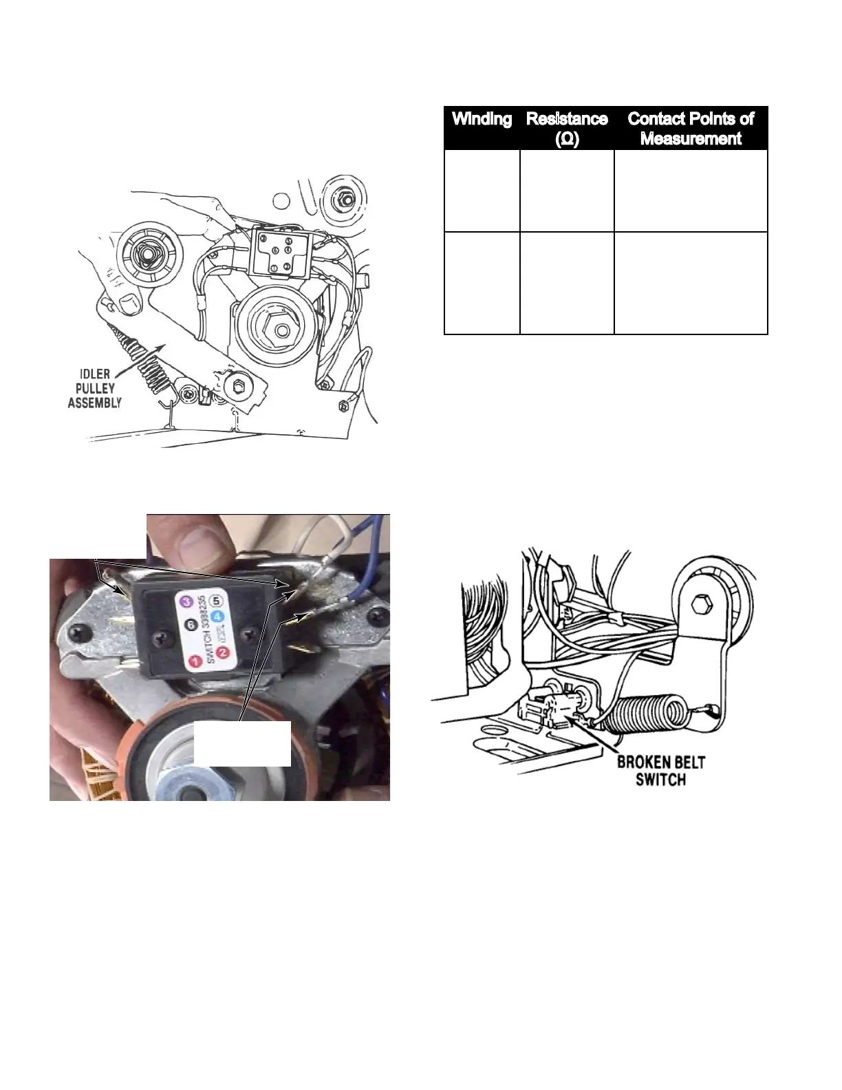
Wires are removed directly from the Motor
Switch (see illustration below).
Check for the resistance values of the
motor’s Main and Start winding coils as
shown below.
NOTE: Main and Start winding coils must
be checked at the motor.
2.
3.
4.
MAIN
14.8 -
15.2 Ω
Blue and White
wires coming out
of the motor.
START
14.8 -
15.2 Ω
Blue and Violet
wires coming out
of the motor.
• If the resistance at the motor is correct,
there is an open circuit (infinite Ω) between
the motor and machine control electronics.
Check for failed belt switch.
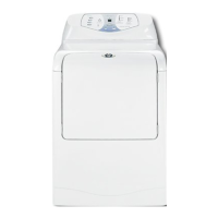
Check the belt switch by measuring
resistance between the belt switch wires,
as shown below, while pushing up the idler
pulley. Isolate the switch by taking the
wire connector from the belt switch off the
terminal at the switch or the motor.
• If the resistance reading goes from infinity
to a few ohms as pulley arm closes the
switch, belt switch is OK. If not, replace the
belt switch.
• If belt switch is OK and there is still an
open circuit (infinite Ω), check and repair the
wiring harness.
• If the Start winding is in question and the
resistance is much greater than 15.2 Ω,
replace the motor.
5.
Main
Winding
Start
Winding