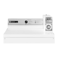
3-4
cumulative timer and can have as many as
11 cycles loaded at any one time by pushing
the actuator on the timer multiple times or by
using the Coin slide multiple times.
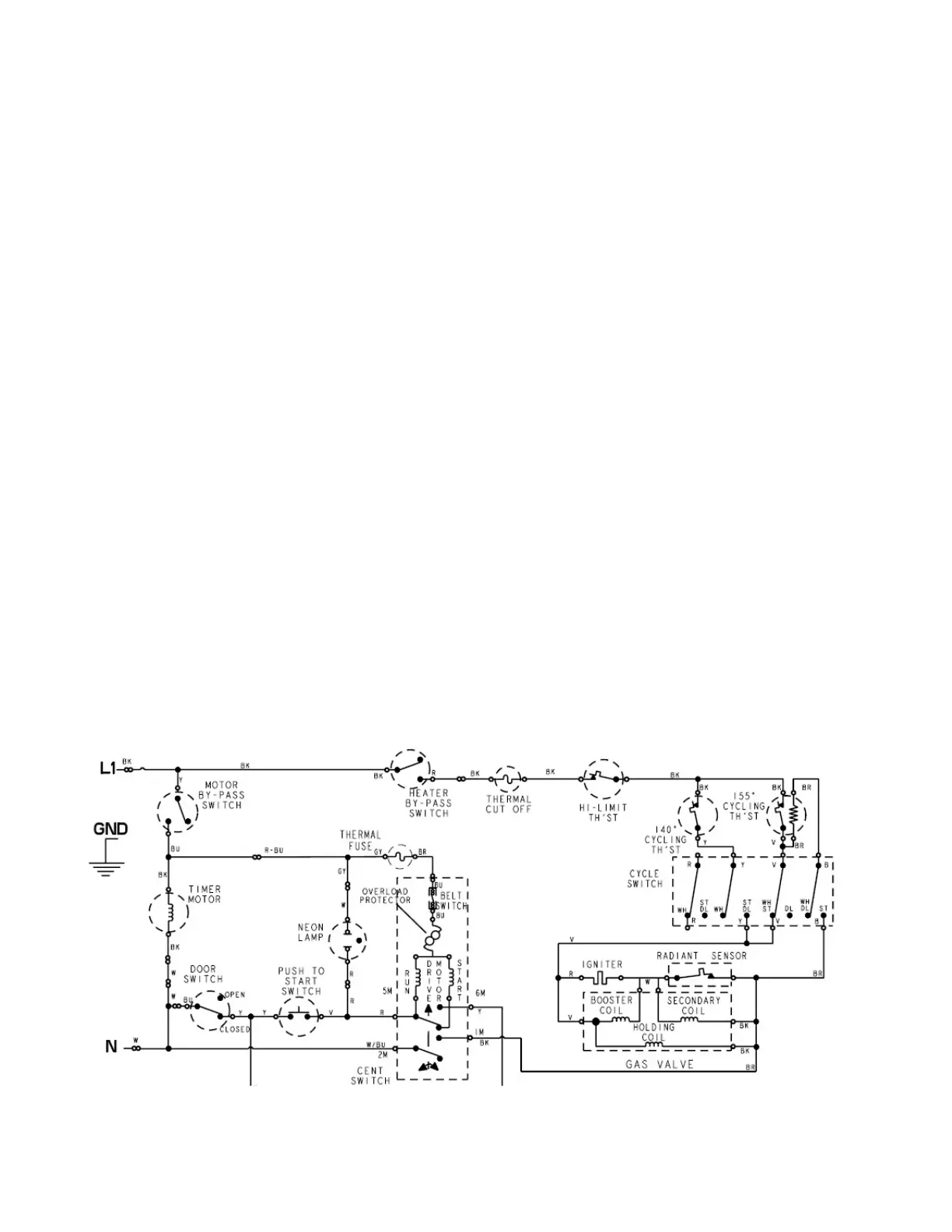
In this diagram we can see that the Cycle
Selector switch will determine which Cycling
Thermostat will be in the circuit and whether
the bias heater in the 155°F T/stat will be used
if medium heat is required.
We notice that the Thermal fuse is now in
series with the Broken Belt switch, the Motor
Overload and the Motor windings instead of in
the Heater circuit. Otherwise the operation is
similar to the PD models.
With all pay for use commercial dryers,
whenever the power is supplied to the dryer
and the cycle has been started, time continues
to count down even if the cycle is interrupted
by the opening of the door.
Stack dryers set for On Premises Laundry
(OPL), which are micro-processor controlled
dryers set for free vend; when a cycle is
interrupted with a door opening, that cycle will
be cancelled, and a new full cycle will need to
be started if additional dry time is required.
The broken belt switch is in series with the
motor and has one of its leads connect directly
to a terminal on the motor thermal overload.
If either the broken belt switch or the motor
thermal overload opens the circuit, it will stop
the motor, which in turn will cause the motor
centrifugal switch to open and change the
positions of the MOtor switch, opening motor
switch 1 to 2, which causes an open in the
neutral in the gas coil circuit and L2 of an
electric element circuit.
CS & MN models are controlled differently,
as there is no micro-processor to control
the functions. A mechanical timer and
manually activated selector switches act as
the user interface to communicate the user
programming to the dryer. The addition of a
Start Switch is also seen on mechanically
controlled dryers. Shown here is the CS model
wire diagram. The Motor & Heater Bypass
Switches are located on the timer, and are
closed when the timer is mechanically pushed
to the start position by pushing the coin slide
in. At the same time the timer is set for a full
cycle and timing is determined by the amount
of pins on the timer cam (factory preset
with the 4 pin 45 min cam). This timer is a
3M