4-5
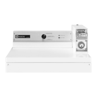
Remove the ’U’ shaped brass colored drive
cam from the timer shaft as well.
Mate the ’U’ shaped drive cam with the
matching slots in the new timing cam.
There are two sizes of slots on the cam
that match the sizes of the pins on the ’U’
shaped drive.
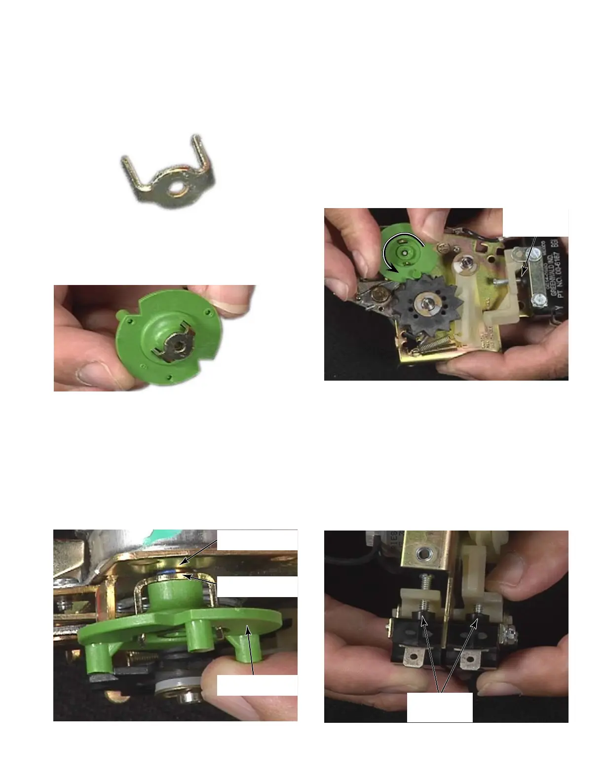
Reinstall the assembled timing cam onto the
’D’ shaped timer shaft.
As the cam is sliding down the timer shaft,
align the ’V’ notch with the ’V’ spoke to allow
the cam to fully seat on the timer.
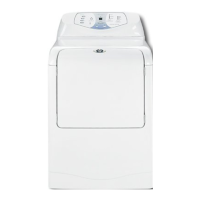
The drive cam must come in contact with
the timer body to be fully seated and
installed, and avoid free vends.
4.
5.
6.
7.
8.
Timer Body
Drive Cam
Timing Cam
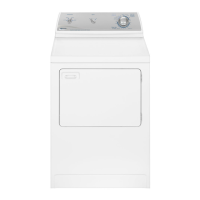
Remove any accumulated time by manually
rotating the timing cam counter-clockwise
until the both the A & B switches are
depressed. This must be done gently as
only slight pressure on the timing cam can
over rotate the cam and cause the switches
to be activated and add another vend cycle
to the timer.
If the switch lever does release the switch
button then continue turning the timing cam
until the timing cam pin approaches the
bottom of the next ’v’ in the spokes of the
top black timer wheel.
Notice the switch arms will move to
depress both of the switches, stop at the
point when both A & B switches are pressed
and their respective contacts are opened, to
have all time removed from the timer.
9.
10.
11.
A & B
Switches
A & B
Switches