October 2008 "3072ES / 3772ES / 3772ES HD" Service & Parts Manual
Page 1-4
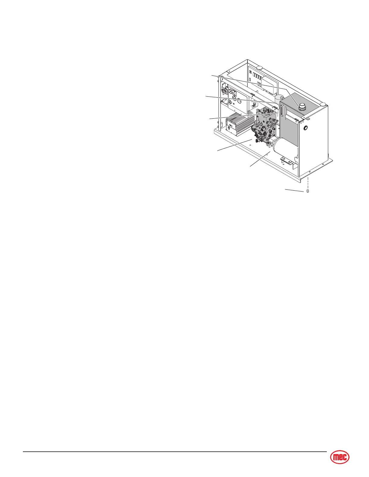
ART_2547
1
5
Hydraulic
Pump
Drain Plug
Hydraulic
Manifold
Sight
Gauge
Hydraulic
Fluid Filter
Hydraulic
Filler Cap
HYDRAULIC SYSTEM COMPONENTS
Hydraulic Reservoir Assembly
This consists of the reservoir, a filler cap with
breather, a drain plug, a sight gauge, and a
bypass filter with a 10 micron filter element.
Perform the following weekly:
• Check reservoir for signs of leakage.
Hydraulic Filter
All machines are produced with a filter. It is a
10 micron spin-on, bypassing filter. When the filter
is clogged, hydraulic flow bypasses the filter
element.
Perform the following every six (6) months or
500 hours:
The filter element must be changed. Extremely dirty
conditions may require that the filter be replaced
more often.
Hydraulic Pump
Note: Refer to
Hydraulic Manifold
and
Relief Pressure Adjustment Procedure
.
Refer to
Section 3
for Remove and Replace instructions.
An electric motor drives the fixed displacement, gear pump. The pump provides hydraulic fluid flow to
operate the machine functions at 8.0 g.p.m. (30.28 l.p.m.) at 3000 r.p.m. There are no adjustments on
the pump. The pump provides power for the lift, drive, brake and steering functions.
WHEEL DRIVE
Note: Refer to
Section 3
for Remove and Replace instructions.
There are four (4) hydraulic, fixed-displacement gear wheel motors to provide power to all four wheels
[two (2) front and two (2) rear].
Dynamic Braking Circuit
The two rear wheel motors have integral brakes that are spring held. Hydraulic pressure developed in
the drive circuit, during drive mode, releases the brakes. A fixed orifice in the brake circuit controls the
deceleration rate and initiates a smooth stop.