October 2008 "3072ES / 3772ES / 3772ES HD" Service & Parts Manual
Page 4-30
No operation from
upper or Upper
Control station
Main battery switch turned off
Emergency switch pushed in or Ignition
switch turned off
Batteries Discharged
Blown 300 AMP fuse
Circuit breaker tripped
Damaged Upper Controls box harness
Other fault in system monitored by GP400
Located left of Lower Controls
Upper or lower Emergency Stop switch will cut all power as will the
ON/OFF switch in the Platform Controls box
Will receive 4-4 or 7-7 flash code on GP400.
Clean, service and charge batteries.
Located left of lower controls.
Check motor amperage draw.
Will receive 7-7 flash code on GP400.
Located in Lower Controls panel.
Possible catastrophic failure within motor controller.
Inspect from harness plug to terminal strip under platform
May receive 6-6 flash code on GP400 (CAN-bus)
Check HELP and MODE message on EZ-Cal or check flash code error
General Power Issue
Functions from Upper
Controls but not from
Upper Controls
Interlock switch (Joystick)
CAN-bus damaged
Check power to RED wire (power to switch) and power to PURPLE wire
(power out of switch) at Joystick plug
Check HELP or MODE message on EZ-Cal
continued…
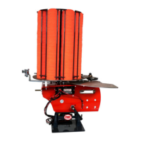
TROUBLE TABLE
The following chart is a guide to help the technician find the area of a problem. In order to befefit from
the information, you are advised to fully assess the symptoms by operating all machine functions.
There may be some functions that operate while others may not. Record this information and proceed
down the left-hand column until you find the failure scenario that best fits the problem. Refer to the
information provided to the right for possible causes and remidies. This unit contains a Microproces-
sor based control system which contains various safety features designed to protect itself and the
operator in the event of a failure.
The EZ-cal scan tool will provide the technician with detailed information related to the failure. It is
strongly recommended that the technician use the EZ-cal to read any displayed messages before
proceeding to use this Troubleshooting chart.
Information on the use of the EZ-cal tool plus helpful Flow Charts and graphs can be found earlier in
the troubleshooting section. You are advised to read and faliliarize yourself with all of the information
provided in the troubleshooting section before attempting to diagnose or repair the 3072ES, 3772ES
models.
PROBLEM REMEDY/SOLUTIONPOSSIBLE CAUSE
TROUBLE
Table