October 2008 "3072ES / 3772ES / 3772ES HD" Service & Parts Manual
Page 3-10
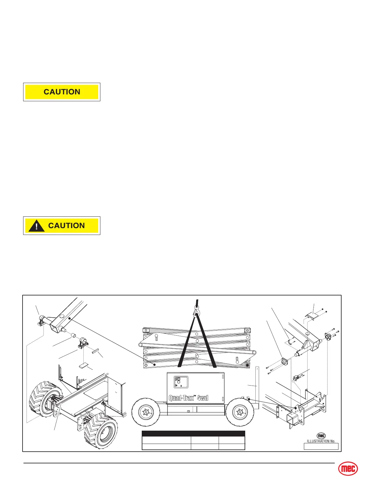
SCISSOR BEAM ASSEMBLY
Note: Refer to
Parts Section C
for detailed parts list and illustration.
Clean the scissor assembly once a year or as necessary and inspect along the beam surfaces, espe-
cially the welds and brackets.
• Clean all fittings before disconnecting hoses.
• Tag hoses for proper reassembly.
• Plug all openings to prevent contamination.
Scissor Beam Removal
1. Remove the platform and ladder.
2. Disconnect hoses and wires and cables
3. Attach a suitable lifting device to the scissor assembly.
4. Remove the Limit Speed switch cover.
5. Remove the bolts from the Limit Speed switch bracket and move the switch and bracket out of
the way.
6. Remove the stationary mounts.
7. Carefully lift until the rear of the scissor assembly is clear.
8. Slide the scissor assembly to the front until the slide blocks exit the end of the slide track.
The scissor assembly may shift suddenly upon clearing the slide track.
9. Lift the scissor assembly.
10. Remove slide blocks, bearings, and wear pads.
11. Clean all parts before installation. Replace worn or damaged parts with new parts.
12. Installation is reverse of removal.
ART_2570
TORQUE Ft. lbs. Nm
Stationary Mount Bolts 86 - 96 116 - 180
Ladder Mount Bolts 86 - 96 116 - 180
Stationary Mount
Top Wear Pad
Bottom Wear Pad
Slide Block
Slide Block
Bearing
Slide Track
Ladder
Limit Speed Cam
Switch Cover
Limit
Speed
Switch