"3072ES / 3772ES / 3772ES HD" Service & Parts Manual October 2008
Page 4-5
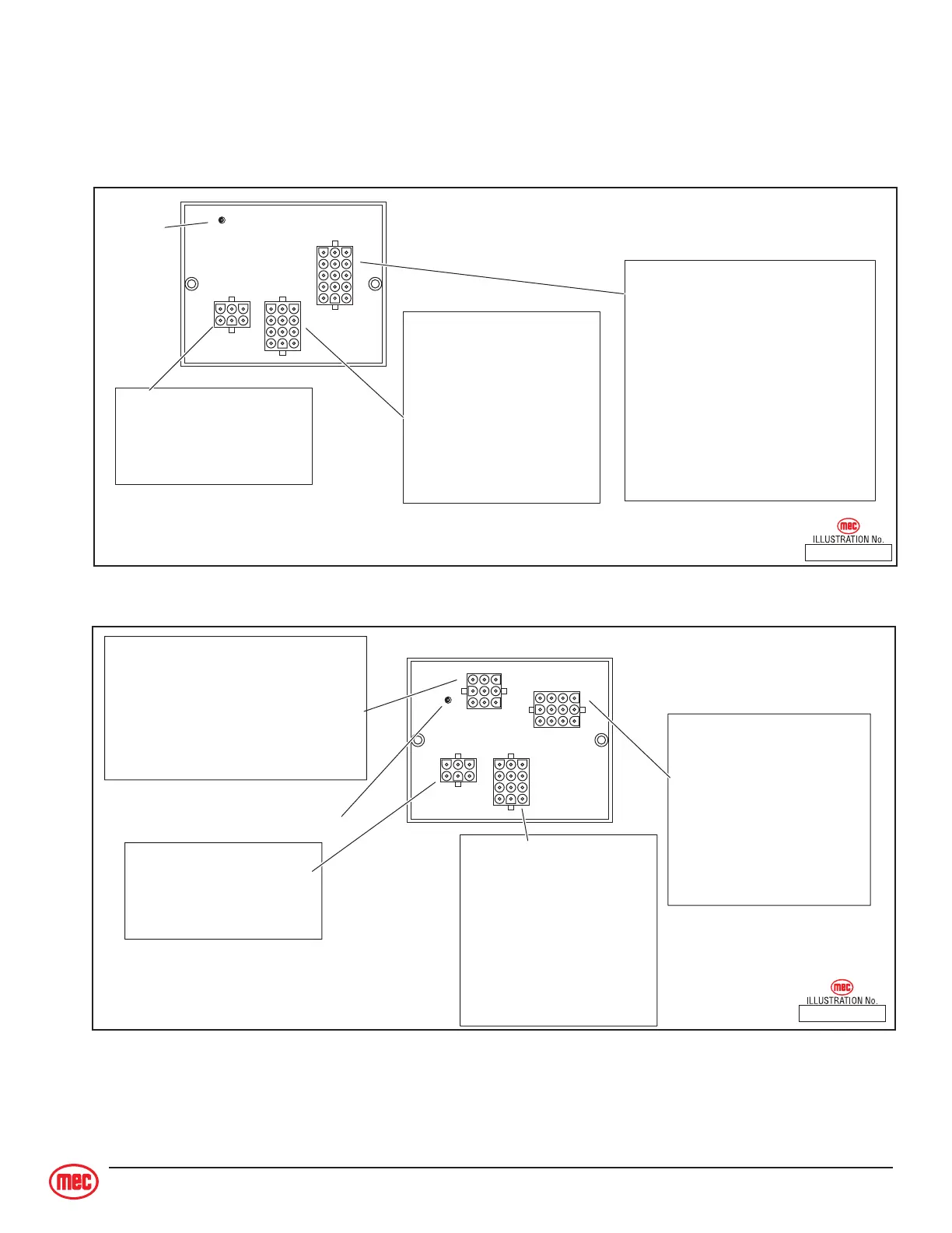
Matrix Module
Located inside the upper control box, the Matrix Module receives inputs from upper control switches
and communicates them to the GP400.
1
10
3
13
1315
13
46
12
Diagnostic
LED
P3-1 — High Speed
P3-2 — Switch Supply
P3-3 — not used
P3-4 — Level Indicator Lamp
P3-5 — Alarm
P3-6 — DriveEnabled Lamp (Outriggers Option)
P3-7 — not used
P3-8 — DRIVE
P3-9 — LIFT
P3-10 — not used
P3-11 — not used
P3-12 — not used
P3-13 — not used
P3-14 — Outriggers UP Switch
P3-15 — Outriggers DOWN Switch
P1-1 — 12 Volts DC INPUT: Power-up
P1-2 — not used
P1-3 — CAN BUS H
P1-4 — Ground
P1-5 — not used
P1-6 — CAN BUS L
P2-1 — FORWARD / DOWN
P2-2 — REVERSE / UP
P2-3 — STEER Left
P2-4 — STEER Right
P2-5 — Enable Bar
P2-6 — Potentiometer
P2-7 — not used
P2-8 — not used
P2-9 — not used
P2-10 — Potentiometer
P2-11 — Potentiometer
P2-12 — Switch Supply
Matrix Module (inside Upper Control Box)
21 510 410
Serial Number 11211001 – 11211036
ART_2574
ART_2575
Matrix Module (inside Upper Control Box)
21 510 411
Serial Number 11211037 - UP
1
10
3
13
46
12
1
10
3
12
1
7
3
9
Diagnostic
LED
P4-1 — not used
P4-2 — not used
P4-3 — not used
P4-4 — Level Indicator Lamp
P4-5 — Alarm
P4-6 — DriveEnabled Lamp (Outriggers Option)
P4-7 — not used
P4-8 — not used
P4-9 — not used
P3-1 — High Speed
P3-2 — Switch Supply
P3-3 — not used
P3-4 — DRIVE
P3-5 — LIFT
P3-6 — NOT USED
P3-7 — not used
P3-8 — not used
P3-9 — not used
P3-10 — Outriggers UP Switch
P3-11 — Outriggers DOWN Switch
P3-12 — not used
P1-1 — 12 Volts DC INPUT: Power-up
P1-2 — not used
P1-3 — CAN BUS H
P1-4 — Ground
P1-5 — not used
P1-6 — CAN BUS L
P2-1 — FORWARD / DOWN
P2-2 — REVERSE / UP
P2-3 — STEER Left
P2-4 — STEER Right
P2-5 — Enable Bar
P2-6 — Potentiometer
P2-7 — not used
P2-8 — not used
P2-9 — not used
P2-10 — Potentiometer
P2-11 — Potentiometer
P2-12 — Switch Supply