PROBLEM REMEDY/SOLUTIONPOSSIBLE CAUSE
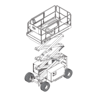
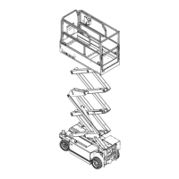
October 2008 "3072ES / 3772ES / 3772ES HD" Service & Parts Manual
Page 4-32
Drive
No drive function 1 or more outriggers deployed partially or
fully
(outrigger equipped models only)
Outrigger switch/s inoperative
Drive valve not shifting
Drive system shut down or interrupted
Check for GREEN LED on upper control box
Operate outrigger retract switch until electric automatically turns off
Check enable light on platform control box
Check outrigger switches located on top of each outrigger jack
Check switch inputs using EZ-Cal (EZ-Cal ID# 2d7 – 2d10)
Check connections at valve
Check drive valve for contamination
Check HELP and MODE message on EZ-Cal
No drive elevated
Slow drive with
Platform stowed
Drive in one direction
only
continued…
Unit out of level
Low battery Voltage
System Interuption
Alarm will sound
Lower and reposition the machine.
Check battery voltage with multi-meter or EZ-Cal.
Clean, service, charge batteries.
Check HELP and MODE message on EZ-Cal
High torque enabled
Limit switch not functioning
Malfunctioning rear wheel bypass valve
Wheel motors not functioning correctly
Check Speed/Torque switch on platform controls
Check limit switch located on left rear of base
Check limit switch input with EZ-Cal (EZ-Cal ID# 2d5)
Located on rear wheels only
Check by replacing valves.
Inspect wheel motors for excessive bypass.
Poor gradability
performance
High or mid speed enabled
Batteries discharged
Wheel motors not functioning correctly
Malfunctioning rear wheel bypass valve
Malfunctioning series parallel valves
Worn hydraulic pump
Check Speed/Torque switch on platform controls
Check battery voltage with multi-meter or EZ-Cal.
Clean, service, charge batteries.
Inspect wheel motors for excessive bypass.
Located on rear wheels only
Check electrical by disconnecting valves.
Check function by replacing valves.
Located on top of main hydraulic manifold
Check with flow meter or replace pump.
Drive valve SVD1 not energized in one
direction
Counterbalance valve CBV1 or CBV2 not
functioning correctly
No output from GP400
Check 12 volts to appropriate coil
Check coil
Check valve function
Swap counterbalance valves to see if functioning direction changes.
Scan using EZ-Cal and troubleshooting charts
EZ-Cal chart ID# 4f-7 – FWD or 2f-9 – Reverse
TROUBLE
Table
continued