MT7620 PROGRAMMING GUIDE
Integrated 802.11n MAC/BBP and 2.4 GHz RF/FEM Router-on-a-Chip
2.14.3 I
2
S Signal Timing For I
2
S Data Format
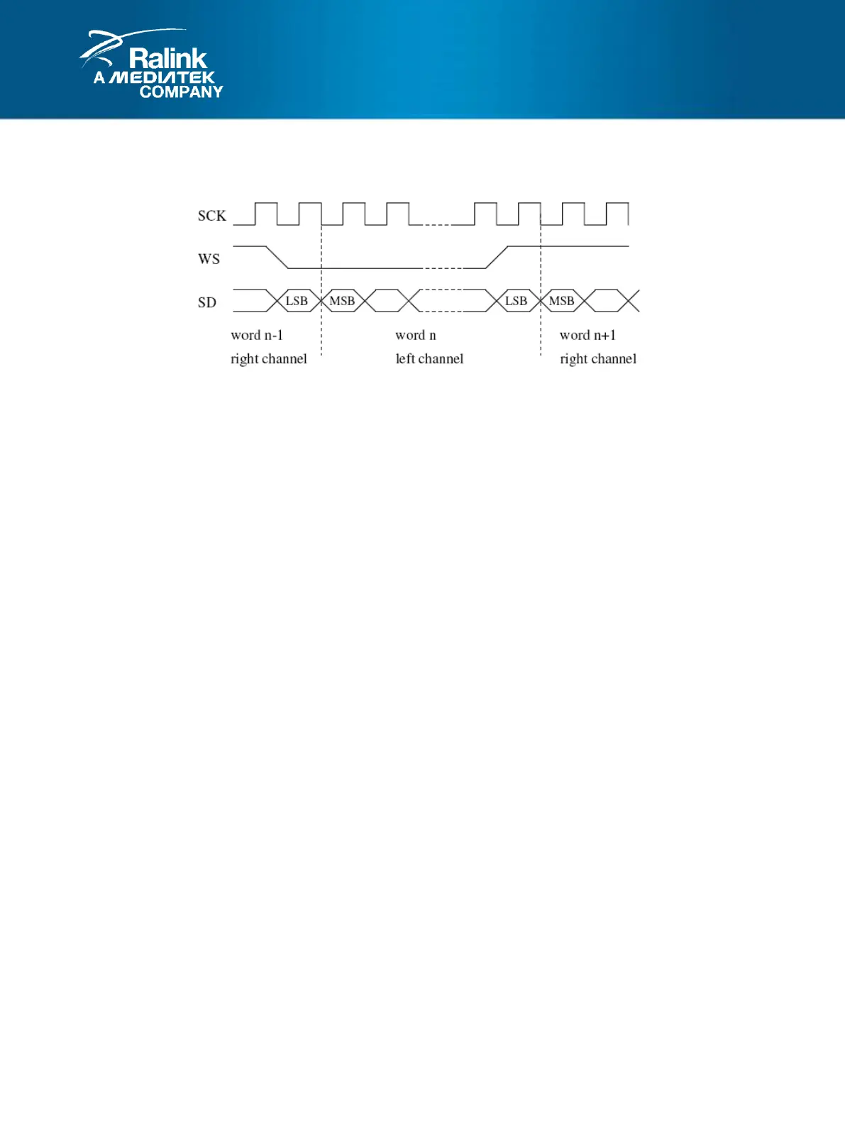
Figure 2-15 I2S Transmit/Receive
Serial data is transmitted in 2’s complement with the MSB first. The transmitter always sends the MSB of the
next word one clock period after the WS changes. Serial data sent by the transmitter may be synchronized
with either the trailing (HIGH-to-LOW) or the leading (LOW-to-HIGH) edge of the clock signal. However, the
serial data must be latched into the receiver on the leading edge of the serial clock signal, and so there are
some restrictions when transmitting data that is synchronized with the leading edge.
The word select line indicates the channel being transmitted:
WS = 0; channel 1 (left)
WS = 1; channel 2 (right)
WS may change either on a trailing or leading edge of the serial clock, but it doesn’t need to be symmetrical. In
the slave, this signal is latched on the leading edge of the clock signal. The WS line changes one clock period
before the MSB is transmitted. This allows the slave transmitter to derive synchronous timing of the serial data
that will be set up for transmission. Furthermore, it enables the receiver to store the previous word and clear
the input for the next Word.