MT7620 PROGRAMMING GUIDE
Integrated 802.11n MAC/BBP and 2.4 GHz RF/FEM Router-on-a-Chip
2.11.5 PCM Configuration
2.11.5.1 PCM Initialization Flow
1. Set PCM_CFG
2. Set CH0/1_CFG
3. Write PCM data to FIFO CH0/1_FIFO
4. Set GLB_CFG to enable the PCM and channel.
5. Set dividor clock
6. Enable clock
7. Monitor FF_STATUS to receive/transmit the other PCM data.
2.11.5.2 PCM Configuration Examples
Below are some examples of PCM configuration.
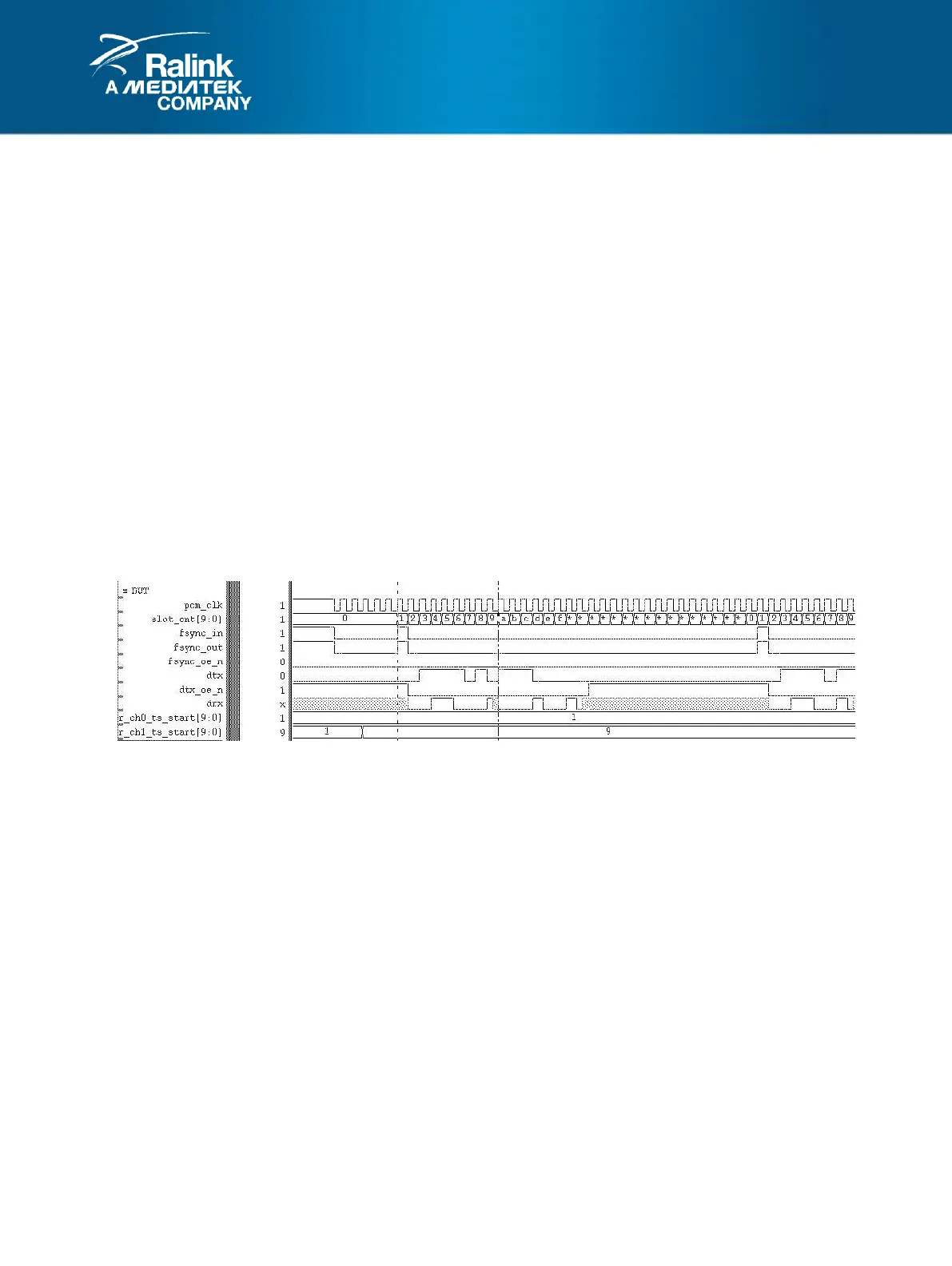
Case 1:
CFG_FSYNC Register: CFG_FSYNC_EN = 0 (PS: fsync is always driven at SLOT_CNT=1)
CH0_CFG Register: TS_START=1
CH1_CFG Register: TS_START=9
PCM_CFG Register: LONG_FSYNC=1’b0, FSYNC_POL=1’b1, DRX_TRI=1’b0, SLOT_MODE=3’b0
Case 2:
CFG_FSYNC Register: CFG_FSYNC_EN = 1, START_LOC=0, interval=16
CH0_CFG Register: TS_START=1
CH1_CFG Register: TS_START=17
PCM_CFG Register: LONG_FSYNC=1’b0, FSYNC_POL=1’b1, DRX_TRI=1’b0, SLOT_MODE=3’b0, RAW16-bits
 Loading...