MT7620 PROGRAMMING GUIDE
Integrated 802.11n MAC/BBP and 2.4 GHz RF/FEM Router-on-a-Chip
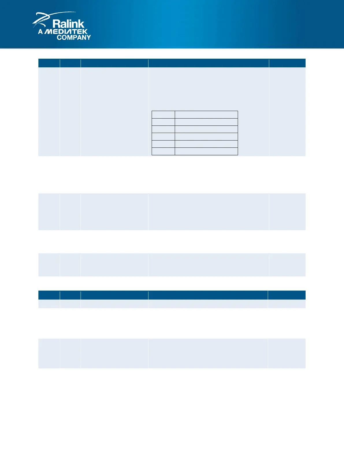
Loopback Mode Enable
0: Normal Operation.
1: The UART is put into loopback mode, and
used for self-testiing. The TXD pin is driven
high; the TXD signal connections are made
internally.
OUT2 Pin Value
0: OUT2N pin is driven to a high level.
1: OUT2N pin is driven to a low level.
NOTE: This bit is only functional in loopback
mode.
OUT1 Pin Value
0: OUT1N pin is driven to a high level.
1: OUT1N pin is driven to a low level.
NOTE: This bit is only functional in loopback
mode.
RTSN1 Pin Value
0: RTSN pin is driven to a high level.
1: RTSN pin is driven to a low level.
DTRN 1 Pin Value
0: DTRN pin is driven to a high level.
1: DTRN pin is driven to a low level.
53. LSR: Line Status Register (offset: 0x001C)
Error in FIFO
Indicates that a FIFO contains data which was
received with a parity error, framing error, or
break condition.
Transmit Shift Register Empty
Indicates that the transmit shift register is
empty. This bit is reset when data is written to
the transmit buffer register (TBR).
Transmit Holding Register Empty
Indicates that the transmitter holding register is
empty. This bit is reset when data is written to
the transmit buffer register (TBR).