VM600 MPS hardware manual (standard version) MAMPS-HW/E 4 - 11
Edition 17 - February 2018
Inputs and outputs
MPC4 / IOC4T CARD PAIR
Only the input signal frequency is of interest for tacho processing, that is, the speed inputs
are used only to detect the edges of the signal. The edge of detection (rising or falling) is
software selectable.
The speed inputs can handle either a "one per revolution" (1/REV) phase signal coming from
a protrusion or notch on the shaft, or a speed signal generated by a toothed wheel (more than
one impulse per revolution).
Depending on the sensor and/or signal conditioner type used, 2-wire or 3-wire transmission
lines can be connected to the speed/phase reference inputs of an MPC4 / IOC4T card pair.
NOTE: See 9 Configuration of MPC4 / IOC4T cards for further information on powering
sensors and associated electronic hardware.
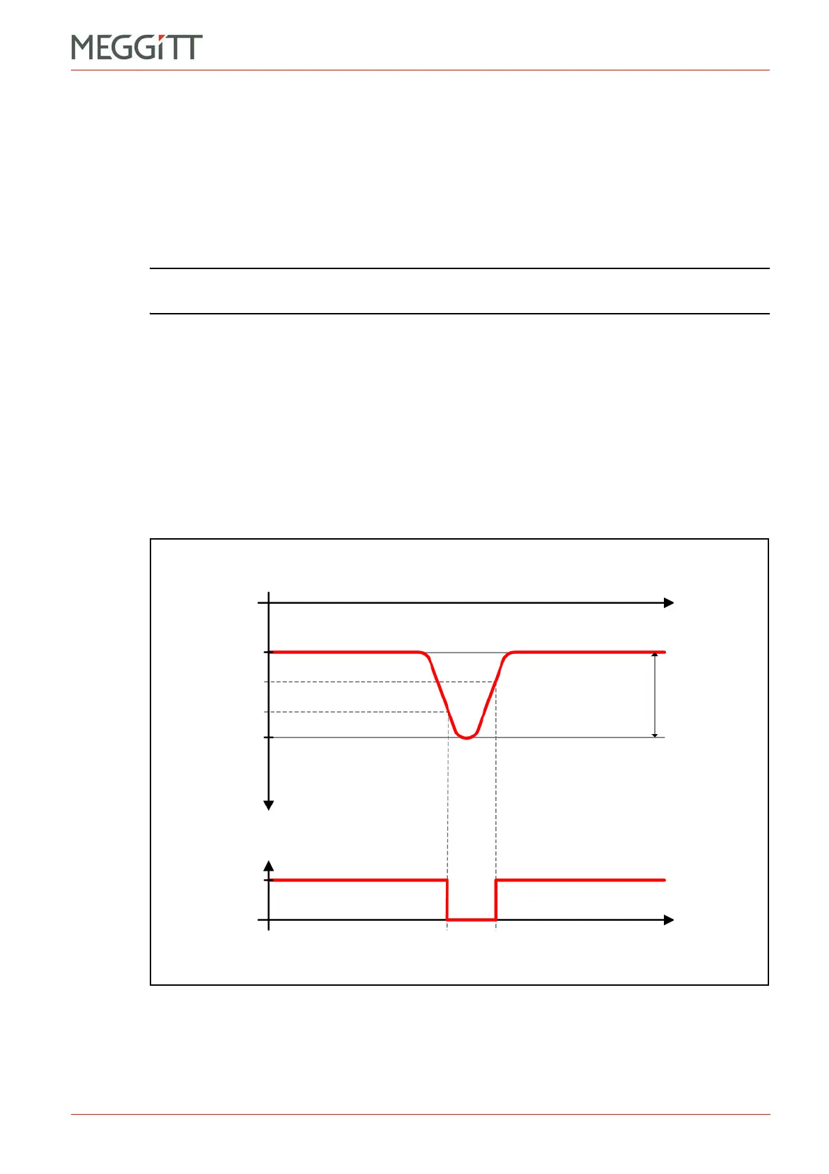
4.4.2.1 Trigger thresholds
As shown in Figure 4-5, the trigger thresholds for a speed/phase reference input signal
depend on the peak to peak amplitude of the input signal.
VT+, the trigger threshold on the falling edge of the input signal, is calculated as follows:
VT+ = V
PEAK
+ (V
PEAK+
V
PEAK
)
VT, the trigger threshold on the rising edge of the input signal, is calculated as follows:
VT =V
PEAK
+ (V
PEAK+
V
PEAK
)
For example, with an input signal that pulses from 7 V to 15 V (that is, 8 V
PEAK-PEAK
):
VT+ = 7V + ( (15 V) (7V) ) = 7V + (8V) = 12.33 V
VT = 7V + ( (15 V) (7V) ) = 7V + (8V) = 9.66 V
Figure 4-5: Trigger thresholds derived from speed/phase reference inputs
Speed signal
input
Time
Trigger signal
Time
+5 V
V
PEAK+
V
PEAK
V
T
V
T+
0V
0V
V
PEAK-PEAK
 Loading...


