VM600 MPS hardware manual (standard version) MAMPS-HW/E 9 - 33
Edition 17 - February 2018
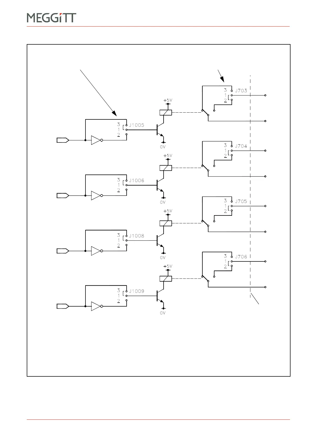
Configuring the four local relays on the IOC4T
CONFIGURATION OF MPC4 / IOC4T CARDS
Figure 9-23: Electrical diagram showing jumpers used to configure relays as NE/NDE and NO/NC
Jumpers J100x used to
select relay NE/NDE
Control signal
(see note 1)
Control signal
(see note 1)
Control signal
(see note 1)
Control signal
(see note 1)
Relay RL1
Relay RL2
Relay RL3
Relay RL4
IOC4T
panel
Notes
1. Specific alarms (A+, D and so on) generated by the corresponding MPC4 card can be selected as the control
signal using the VM600 MPSx software. The normal state of the control signal is shown in Table 9-4.
2. See Table 9-5 for information on how to set the jumpers to obtain the desired operation.
Jumpers J70x used to
select relay contact NO/NC
 Loading...


