9 - 34 VM600 MPS hardware manual (standard version) MAMPS-HW/E
Edition 17 - February 2018
Configuring the four local relays on the IOC4T
CONFIGURATION OF MPC4 / IOC4T CARDS
Configuration examples for relay RL1 using a a control signal with a normal state of 1
(see Table 9-4):
a. To configure RL1 to act as a normally energised (NE) relay with normally closed
(NC) contacts (see Table 9-5):
• Jumper J1005 has contacts 1-3 closed.
• Jumper J703 has contacts 1-2 closed.
In this case, RL1 provides a closed circuit when there is no alarm. It provides an
open circuit in the event of an alarm or power supply failure.
b. To configure RL1 to act as a normally de-energised (NDE) relay with normally closed
(NC) contacts (see Table 9-5):
• Jumper J1005 has contacts 1-2 closed.
• Jumper J703 has contacts 1-3 closed.
In this case, RL1 provides a closed circuit when there is no alarm or when there is a
power supply failure. It provides an open circuit in the event of an alarm.
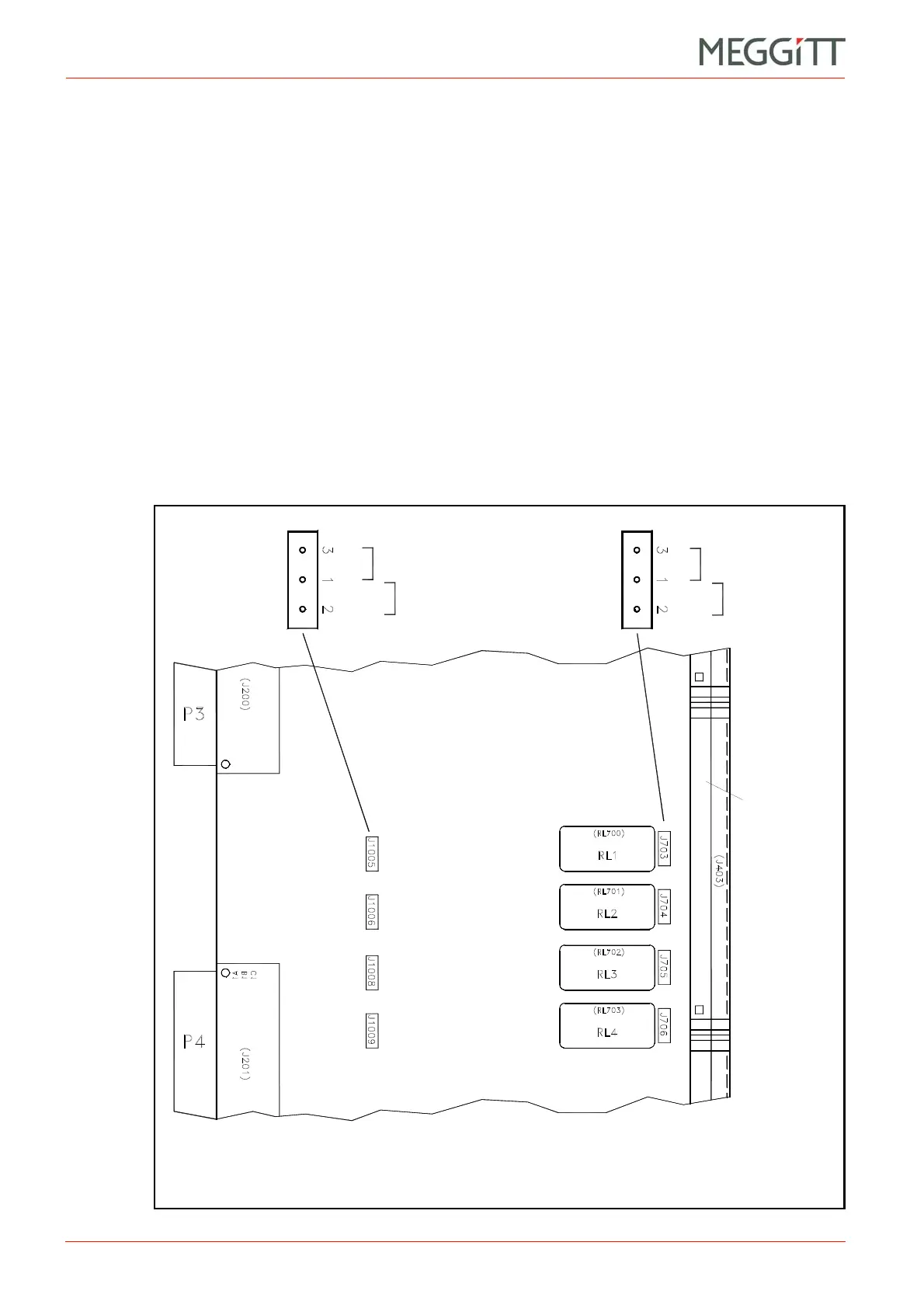
Figure 9-24: Position of jumpers used to configure the IOC4T local relays as NE or NDE
Connector
J2
(Top of card)
(Bottom of card)
Note: The J100x and J70x
jumper settings depend on the
normal state of the control
signal (see Table 9-4) and the
required operation of the relay
(see Table 9-5).
 Loading...


